Uncertain Gain and Phase
Use the umargin control
design block to model gain and phase variations in feedback loops. Modeling gain and phase
variations in your uncertain system model lets you verify stability margins during
robustness analysis or enforce them during robust controller design.
To add gain and phase uncertainty to a feedback loop, you incorporate
umargin blocks into an uncertain state-space (uss)
model of the closed-loop system. umargin is a SISO control design block,
representing gain and phase variation at a single location in a single feedback loop. To
model gain and phase uncertainty in MIMO feedback systems, insert a separate
umargin object at each location in the system at which you want to
introduce gain and phase uncertainty.
Disk Model of Gain and Phase Uncertainty
umargin models gain and phase variations in an individual feedback channel as
a frequency-dependent multiplicative factor F(s)
multiplying the nominal open-loop response L(s), such
that the perturbed response is
L(s)F(s).
The factor F(s) is parameterized by:
In this model,
δ(s) is a gain-bounded dynamic uncertainty, normalized so that it always varies within the unit disk (||δ||∞ < 1).
ɑ sets the amount of gain and phase variation modeled by F. For fixed σ, the parameter ɑ controls the size of the disk. For ɑ = 0, the multiplicative factor is 1, corresponding to the nominal L.
σ, called the skew, biases the modeled uncertainty toward gain increase or gain decrease.
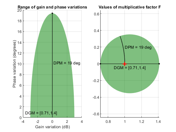
The factor F takes values in a disk centered on the real axis and
containing the nominal value F = 1. The disk is characterized by its
intercept DGM = [gmin,gmax] with the real axis. gmin
< 1 and gmin > 1 are the minimum and maximum relative changes in gain
modeled by F, at nominal phase. The phase uncertainty modeled by
F is the range DPM = [pmin,pmax] of phase values
at the nominal gain (|F| = 1). For instance, in the following plot, the
right side shows the disk F that intersects the real axis in the interval
[0.71,1.4]. The left side shows that this disk models a gain variation of ±3 dB and a phase
variation of ±19°.
F = umargin('F',1.4125)
plot(F)
When you create a umargin block, you specify the amount of uncertainty by
specifying DGM. Use getDGM to
translate specific amounts of gain and phase variations in to a suitable
DGM range that captures these variations. For more information about
the uncertainty model used by umargin, see Stability Analysis Using Disk Margins.
You can visualize the ranges of gain and phase uncertainty represented by a
umargin object using plot
(umargin).
For examples of creating umargin objects and incorporating them into
uncertain models, see:
Using Gain and Phase Uncertainty
When you have a uss model containing umargin control
design blocks, you can perform robustness and worst-case analysis to examine how gain
and phase variation affects the response of the system. For instance, use robstab and robgain to analyze the robust stability
and robust performance of a system with gain and phase uncertainty. Use wcgain and wcsigmaplot to examine the worst-case responses of the system. For some
examples, see:
Requiring robust stability for a closed-loop system with umargin gain
and phase uncertainty is equivalent to enforcing a disk-based gain margin
[gmin,gmax] and corresponding phase margin. Therefore, you can
use umargin blocks to enforce suitable disk margins when designing
robust controllers with musyn.
For examples, see:
The requirement that a closed-loop system is robust against a
particular amount of gain and phase uncertainty is equivalent to saying that the system
has that amount of gain and phase margin. You can therefore use a
umargin block to check the disk-based stability margins of a system
that also requires robustness against other types of uncertainty. For an example,
see:
Check Robustness to Gain and Phase Variations on the
umarginreference page
See Also
umargin | getDGM | plot
(umargin)