Generate ros2_control Plugin from Simulink
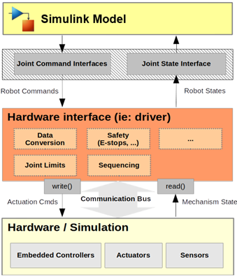
The ros2_control framework provides a generic set of tools to create controllers for various types of physical or simulated robots using ROS 2 network. This topic shows you how to auto-generate C++ code for a controller designed in Simulink®, package and deploy the controller as a ros2_control plugin. The data flow of the controller is shown here:

Configure Controller Model for ROS 2 Deployment
Follow these steps to configure the Simulink controller model for ROS 2 deployment:
From the model toolstrip, selectApps > ROS. This opens the ROS app tab in the toolstrip.
Specify ROS Network option as Robot Operating System 2 (ROS 2).
Specify Deploy To option as Remote Device. In the same drop-down, select Manage Remote Device and specify the ROS 2 device parameters.
Configure ROS 2 Control Interfaces and Dynamic Reconfigurable Parameters
In the controller Simulink model, you must assign each inport and outport to the correct ROS 2 joint interfaces of your robot. You can configure each joint interface on the robot as one of these types:
PositionJointInterfaceVelocityJointInterfaceEffortJointInterfaceAccelerationJointInterface
To open the ROS 2 Control configuration dialog, from the Prepare section under ROS tab, select ROS Control Settings and follow these steps:
Specify the name of the Controller C++ class.
In the Inports tab, for each inport:
Specify the Resource name as the name of the corresponding controllable joint on the robot.
Specify the Resource type as the joint interface for the corresponding joint on the robot.
In the Outports tab, follow the same instructions as step
2.From the Parameters tab, select the Generate as ROS 2 Parameter option for all the parameters in the model that you wish to generate as dynamic reconfigurable parameters in the deployed plugin.
Select Generate ros2_control controller package checkbox.
Click OK to save the settings and close the dialog.
Deploy ROS 2 Control to Remote ROS 2 Device
To deploy the configured controller Simulink model, follow these steps:
Under ROS tab, from the Deploy Type section, select the deployment type as ROS Control Plugin.
Under ROS tab, from the Deploy section, click Build Model.
Click on the View Diagnostics link at the bottom of the model toolbar to see the output of the build process.
After code generation, Simulink transfers the ROS 2 package to the ROS 2 device and builds the colcon workspace on the ROS 2 device.
Integrate and Register Deployed ROS 2 Control Plugin with Robot
To integrate the deployed ROS 2 control plugin with the robot, follow these steps on the remote ROS 2 device:
Navigate to the deployed ROS 2 package source directory in the colcon workspace. The name of the package is same as the Simulink model.
In the
configdirectory, open thecontrollers.yamlfile. Copy the deployed controller definition in the YAML file.In the colcon workspace, navigate to the ROS 2 package source directory of your robot where the controller definition YAML file is present. Paste the copied controller definition in the YAML file.
If you are using a launch file, modify it to launch the generated controller. Alternatively, you can load the controller after launch file executes using controller manager.
Build the ROS 2 package of your robot. This registers the deployed controller plugin with your robot.
Verify the Deployed ROS 2 Control Plugin
Start the robot by launching the corresponding node or launch file. If you are using a simulated robot, you start the Gazebo world with your robot.
Use this command to launch the dynamic parameter reconfigure dialog where you can tune the parameters associated with the deployed controller:
$ ros2 run rqt_reconfigure rqt_reconfiure
rqt_controller_manager to load or unload
the deployed the
controller:ros2 run rqt_controller_manager rqt_controller_manager
Next Steps
For an application of ros2_control plugin generation for 3-D
trajectory control of a UR5e robotic manipulator, see Design and Generate ros2_control Trajectory Controller for UR5e Manipulator Using Simulink.