Main Content

C Data Code Interface Configuration for Model Interface Elements

Configure a model to use a data code interface if you are deploying C code as an application. Code generated for application deployment is optimized to a specific scheduler (single-tasking, rate-monotonic, or concurrent) based on your model configuration.

Model Code Interfaces (Embedded Coder) lists modeling elements that you can use to represent interfaces for interacting with target environment resources. To configure the modeling elements for code generation, in the Code Mappings editor or by using the code mappings programming interface (coder.mapping.api.CodeMapping), you map model interface elements to code definitions.

When configuring a data code interface, you can:

  • Configure default code interface settings that apply throughout a model for categories of data elements. For example, inports is a category of data elements and periodic functions is a category of functions.

  • Configure code interfaces settings that apply to individual data elements.

Migration

When you open a model created in a release before R2020b, Simulink® migrates code definitions, such as embedded signal and parameter objects in the model workspace, to the model code mappings.

For a model configured to use an ERT-based system target file for code generation, if necessary, as part of the migration, Simulink configures the Embedded Coder Dictionary that the model uses. When you save the model, the code mappings are saved as part of the model.

For more information, such as effects of migration and what to consider before migrating, see Migration of Model Data Configurations to Code Mappings.

Code Definitions

For a data code interface configuration, code definitions include storage classes. A storage class defines properties, such as appearance and location, that the code generator uses when producing code for the associated data.

The code generator provides predefined code definitions for data elements. If you have Embedded Coder®, you can use the Embedded Coder Dictionary to create and share code definitions, for example, to standardize code that you generate from multiple models or to create definitions for different application run-time environments. Creating custom definitions enables you to achieve code generation objectives that predefined definitions cannot satisfy. For data elements, you also have the option of creating code definitions created in packages by using Embedded Coder Custom Storage Class Designer.

Code definitions appear in the Code Mappings editor and are accessible by using the code mappings programming interface.

Data Interface Code Mapping Options

Associate elements of a model that represent interfaces with code definitions by using the Code Mappings editor or the code mappings programming interface. The code generator uses the mapped code definitions to determine what the generated interface code should look like and how the code should be packaged.

Simplify the effort of configuring code interfaces by specifying default configurations for the code generator. For data interface configurations, you specify default configurations in the Code Mappings editor on the Data Defaults and Function Defaults tabs or by calling the setDataDefault and setFunctionDefault functions. You can let the code generator establish the default configuration by setting the storage class or function customization template to Default or you can specify a named storage class or function customization template. When you specify Default, the code generator determines how data elements and function prototypes appear in the generated code. When you specify a named storage class or function customization template the code generator applies the settings specified for that code definition.

For individual model elements, you can override the default category code configuration setting. Select the tab that corresponds to the element category or call the corresponding element category setElementCategory function (for example, setInport or setState). For an individual element, you have three configuration options:

  • Let the code generator handle the configuration.

    • For data elements, select or specify Auto. For Auto the data element is subject to code generation optimizations, which can eliminate the element from the code or change the representation of the element. If optimizations do not eliminate the data element, the element acquires the default configuration for the corresponding data category. If a default is not configured for the category (on the Data Defaults tab, category is set to Default), the element appears as a field of a standard data structure in the generated code.

    • For functions, select or specify Default.

  • Map the data or function element to the code definition that is configured as the default for the relevant data or function element category for this model. Specify Model default: storage class or Model default: function-template.

  • Map the data or function element to a named storage class or function customization template that is not labeled as the model default.

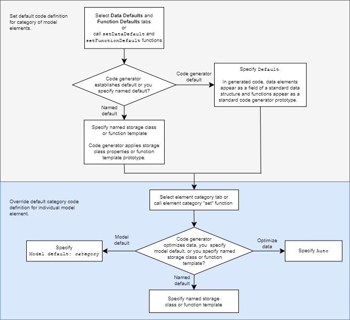
This figure summarizes the relationship between default and individual configuration settings and available choices.

Set default code definition for category of model elements by selecting Data Defaults and Function Defaults tabs. Then, Specify Default or a named storage class or function template. Override default definition for individual model element by selecting the element category tab. Then, specify Model default: category, Auto, or a named storage class or function template.

Data Default Configurations

Reduce the effort of preparing a model for C code generation by specifying default configurations for categories of data elements, for example inports or model workspace parameters, across a model. Applying default configurations can save time and reduce the risk of introducing errors in code, especially for larger models and models from which you generate multi-instance code.

Default configurations apply throughout a model, excluding referenced models. Simulink saves a separate set of code mappings as part of each model in a model reference hierarchy.

If a model includes a significant number of elements of a given category (for example, more than 10), it is more efficient to configure the category by using a default setting, and then override that setting for special cases.

The default settings can help you to reduce manual data entry.

  • As you add blocks to a model, new data elements inherit the default settings.

  • To change code generation settings for many data elements at once, make the changes in one place—the default settings.

  • For efficiency, use naming rules as you make changes elsewhere in the model.

You configure data defaults by using the Code Mappings Editor – C Data Defaults tab or the setDataDefault function.

Model Data Categories

You configure data defaults by using the Code Mappings Editor – C Data Defaults tab or the setDataDefault function. In the Data Defaults tab or function call, you can select or specify these categories of data elements.

Model Element CategoryDescription
InportsRoot-level input ports of a model, such as Inport and In Bus Element blocks.
OutportsRoot-level output ports of a model, such as Outport and Out Bus Element blocks.
Signals, states, and internal dataData elements that are internal to the model, such as block output signals, discrete block states, data stores, and zero-crossing signals.
Shared local data storesData Store Memory blocks that have the block parameter Share across model instances set. These data stores are accessible only in the model where they are defined. The data store value is shared across instances of the model.
Global data storesData stores that are defined by a signal object in the base workspace or in a data dictionary. Multiple models in an application can use these data stores. To view and configure these data stores in the Code Mappings editor, click the Refresh link to the right of the category name. Clicking this link updates the model diagram.
Model parametersParameters that are defined within a model, such as parameters in the model workspace. Excludes model arguments.
External parametersParameters that you define as objects in the base workspace or in a data dictionary. Multiple models in an application can use these parameters. To view and configure these parameters in the Code Mappings editor, click the Refresh link to the right of the category name. Clicking this link updates the model diagram.

Considerations for Configuring Default Code Generation Settings for Data

Before configuring default code generation settings for data elements, take into account the considerations listed in this table.

ConsiderationMore Information
What categories are relevant to your model?The data element categories in the preceding table
Does the model use several instances of data that is in a category? If the answer is yes, applying default mappings is beneficial. Otherwise, consider configuring code generation for each data element individually.
Which storage class aligns with your code generation requirements for each category? Choose Storage Class for Controlling Data Representation in Generated Code
Do you want to prevent optimizations from eliminating specific data from the code? Elimination of Categories of Data by Optimizations

After you configure one or more categories of model elements, setting memory sections and Shared utilities identifier format model configuration parameters has no effect on the model configuration. When you open a coder app, Simulink migrates the model configuration parameter settings to the Code Mappings editor. As part of the migration, Simulink configures the Embedded Coder Dictionary that the model uses, as described in Migration of Memory Section and Shared Utility Settings from Configuration Parameters to Code Mappings (Embedded Coder).

Elimination of Categories of Data by Optimizations

Code generation optimizations can eliminate data from the code, which means your application code cannot interact with the data. For general information about data elimination by optimizations, see How Generated Code Stores Internal Signal, State, and Parameter Data (Embedded Coder).

The optimizations can eliminate data in these categories only:

  • Model parameters

  • Model parameter arguments

  • External parameters

  • Internal data

After eliminating data with optimizations, the code generator applies the default code generation settings in the code mappings to the remaining data. For parameters and signal lines, optimizations can eliminate data for an entire category. If this elimination occurs, default settings that you specify for that category do not apply to data.

To prevent optimizations from eliminating individual data elements, explicitly apply a storage class to the individual element. The storage class controls the appearance of the data in the generated code. To force a data element to use the default storage class that you specify, explicitly apply the storage class Model default. See Choose Storage Class for Controlling Data Representation in Generated Code.

Shared Dictionary Data Defaults

If you link a model to a Simulink data dictionary, which includes a coder dictionary that configures default code definitions for categories of data, you can use the Code Mappings editor to apply the dictionary defaults. In the Code Mappings editor, on the Data Defaults tab, select a category and set the storage class to Dictionary Default. If someone makes a change to the default settings in the shared coder dictionary, the code generator applies the updated default settings when producing code for your model. See Configure Default Code Mapping in a Shared Dictionary (Embedded Coder).

Configurations for Individual Data Elements

After you configure model-wide default settings, you can override the defaults for individual data elements. An individual data element configuration applies to a specific data element in a model. Configure data elements individually when:

  • The model includes a few elements of a given category that have unique source, naming, or placement requirements.

  • You configured default settings and you want to override the default setting for an individual element.

For individual data elements, initially the storage class is set to Auto, which means that the code generator might eliminate or change the representation of relevant code for optimization purposes. If optimizations are not possible, the code generator applies the model default configuration.

  • To avoid optimizations and force the code generator to use the default configuration, set the storage class to Model default.

  • To override the default configuration, specify the storage class that meets the code generation requirements for that data element.

Configure Data

  1. Open the Simulink Coder™ app.

  2. Configure default mappings for categories of data elements. Select Code Interface > Default Code Mappings. In the Code Mappings editor, on the Data Defaults tab,select a model element category and set the storage class. In the Property Inspector, set storage class properties to align with model requirements.

  3. Decide whether to override default configuration settings for individual data elements. If you choose not to override settings, go to step 8.

  4. Identify MATLAB variables that you want to configure individually and store the configurations in the model file. In the Model Explorer, convert the variables to Simulink.Parameter objects. The resulting data objects appear in the Code Mappings editor as model parameters.

  5. Identify signals representing algorithm data that you want to monitor while the generated code executes and configure those signals individually. For each signal that you identify, do one of the following:

    • For signal data that is specific to a model (not shared), add the signals to the Code Mappings editor.

    • For shared signal data, create and configure Simulink.Signal objects.

  6. Configure individual data elements. In the Code Mappings editor, click a category tab, select a data element, and set the storage class. In the Property Inspector, set storage class property values. To change the setting of model configuration parameter Default parameter behavior, click the link indicating the behavior when the storage class is set to Auto. In the Model Configuration Parameters dialog box, change the parameter setting to Tunable or Inline.

  7. To view and configure external data objects that are stored in the base workspace or a data dictionary, in the Code Mappings editor, on the Data Defaults tab, click the Refresh link to the right of the category name.

  8. Generate and review code.

For more details and examples, see:

See Also

|

Related Topics