Log Program Execution Results
Multiple techniques are available by which a program generated by the Simulink®
Coder™ software can save data to a MAT-file for analysis. A generated executable can
save system states, outputs, and simulation time at each model execution time step. The data
is written to a MAT-file, named (by default)
model.matmodel is the name of your model. See Log Data for Analysis for a data logging tutorial.
Note
Data logging is available only for system target files that have access to a file system. In addition, only the RSim target executables are capable of accessing MATLAB workspace data.
For MAT-file logging limitations, see the configuration parameter MAT-file logging.
Log Data for Analysis
Set Up and Configure Model
This example shows how data generated by a copy of the model
slexAircraftExample is logged to the file
myAircraftExample.mat. Refer to Build Process Workflow for Real-Time Systems for instructions on setting up a copy of
slexAircraftExample as myAircraftExample in a
working folder if you have not done so already.
Note
When you configure the code generator to produce code that includes support for data
logging during execution, the code generator can include text for block names in the
block paths included in the log file. If the text includes characters that are
unrepresented in the character set encoding for the model, the code generator replaces
the characters with XML escape sequences. For example, the code generator replaces the
Japanese full-width Katakana letter ア with the escape sequence
ア. For more information, see Internationalization and Code Generation.
To configure data logging, open the Configuration Parameters dialog box and select the
Data Import/Export pane. The process is the same as configuring a
Simulink model to save output to the MATLAB® workspace. For each workspace return variable you define and enable, the
Simulink
Coder software defines a parallel MAT-file variable. For example, if you save
simulation time to the variable tout, your generated program logs the
same data to a variable named rt_tout. You can change the prefix
rt_ to a suffix (_rt), or eliminate it entirely.
You do this by setting model configuration parameter MAT-file variable name
modifier.
To log signals in generated code, use the Data Import/Export model configuration parameters described below or include To File or To Workspace blocks in your model.
Note
MAT-file logging for code generation does not support signal logging. If you enable MAT-file and signal logging by using Data Import/Export model configuration parameters and select signals for logging in the Simulink Editor, when you build the model, the code generator displays this warning:
Warning: MAT-file logging does not support signal logging.
When your model code executes, the signal logging variable 'rt_logsout' will
not be saved to the MAT-file.
In this example, you modify the myAircraftExample model so that the
generated program saves the simulation time and system outputs to the file
myAircraftExample.mat. Then you load the data into the base workspace
and plot simulation time against one of the outputs. The
myAircraftExample model should be configured as described in Build Process Workflow for Real-Time Systems.
Data Logging During Simulation
To use the data logging feature:
Open the
myAircraftExamplemodel if it is not already open.Open the Configuration Parameters dialog box.
Select the Data Import/Export pane. The Data Import/Export pane lets you specify which outport data is to be saved to the workspace and what variable names to use for it.
Set parameter Format to
Structure with time. When you select this format, Simulink saves the model states and outputs in structures that have their names specified in the Save to workspace or file area. By default, the structures arexoutfor states andyoutfor output. The structure used to save output has two top-level fields:timeandsignals. Thetimefield contains a vector of simulation times andsignalscontains an array of substructures, each of which corresponds to a model output port.Select Output. This tells Simulink to save output signal data during simulation as a variable named
yout. Selecting Output enables the code generator to create code that logs the root Output block (alpha, rad) to a MAT-file.Set Decimation to
1.If other parameters are selected, clear them.
Click Apply and OK to register your changes and close the dialog box.
Save the model.
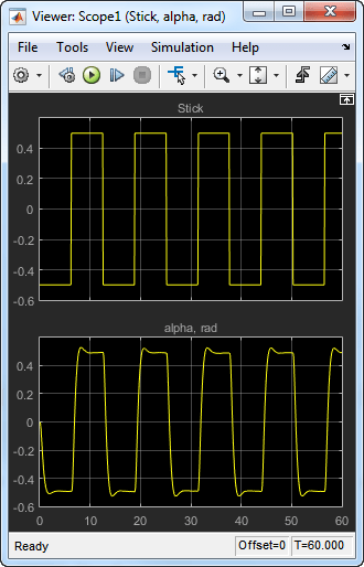
In the model window, double-click the scope symbol next to the Aircraft Dynamics Model block, then simulate the model. The resulting scope display is shown below.
Verify that the simulation time and outputs have been saved to the base workspace in MAT-files. At the MATLAB prompt, type:
Simulink displays:whos yout
Name Size Bytes Class Attributes yout 1x1 10756 struct
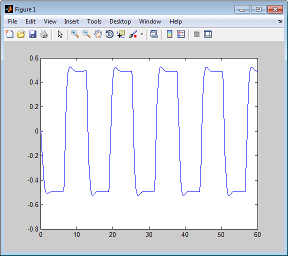
Verify that
alpha, radwas logged by plotting simulation time versus that variable. In the Command Window, type:plot(yout.time,yout.signals.values)

Data Logging from Generated Code
In the second part of this example, you build and run an executable program built by
the code generator for model myAircraftExample. The program outputs a MAT-file containing the simulation time and output you previously examined.
Even though you have already generated code for the myAircraftExample
model, you must now regenerate that code because you have changed the model by enabling
data logging. The steps below explain this procedure.
To avoid overwriting workspace data with data from simulation runs, the code generator modifies identifiers for variables logged by Simulink. You can control these modifications.
Set model configuration parameter MAT-file variable name modifier to
_rt. This adds the suffix_rtto each variable that you selected to be logged in the first part of this example.Click Apply and OK to register your changes and close the dialog box.
Save the model.
Build an executable.
When the build concludes, run the executable program with the command:
!myAircraftExample
The program now produces two message lines, indicating that the MAT-file has been written.
** starting the model ** ** created myAircraftExample.mat **
Load the MAT-file data created by the executable and look at the workspace variables from simulation and the generated program by typing:
load myAircraftExample.mat whos yout*
Simulink displays:
Name Size Bytes Class Attributes yout 1x1 10756 struct yout_rt 1x1 10756 struct
Note the size and bytes of the structures resulting from the simulation run and generated code are the same.
Plot the generated code output by entering the following command in the Command Window:
plot(yout_rt.time,yout_rt.signals.values)
The plot should be identical to the plot that you produced in the previous part of this example.
Tip
For UNIX® platforms, run the executable program in the Command Window with the syntax
!./executable_name. If
preferred, run the executable program from an OS shell with the syntax
./executable_name. For more
information, see Run External Commands, Scripts, and Programs.
Configure State, Time, and Output Logging
The Data Import/Export pane enables a generated program to
save system states, outputs, and simulation time at each model execution time step. The data
is written to a MAT-file, named (by default)
model.mat
Before using this data logging feature, you should learn how to configure a Simulink model to return output to the MATLAB workspace. This is discussed in Save Simulation Data.
For each workspace return variable that you define and enable, the code generator
defines a MAT-file variable. For example, if your model saves simulation time to the
workspace variable tout, your generated program logs the same data to a
variable named (by default) rt_tout.
The code generated by the code generator logs the following data:
Root Outport blocks
The default MAT-file variable name for system outputs is
rt_yout.The sort order of the
rt_youtarray is based on the port number of the Outport block, starting with 1.Continuous and discrete states in the model
The default MAT-file variable name for system states is
rt_xout.Simulation time
The default MAT-file variable name for simulation time is
rt_tout.
Override Default MAT-File Variable Names
By default, the code generator prefixes the text rt_ to the
variable names for system outputs, states, and simulation time to form MAT-file variable
names. To change this prefix for a model, set model configuration parameter
MAT-file variable name modifier to (rt_), a
suffix (_rt), or no modifier
(none). Other system target files might not support this
parameter.
Override Default MAT-File Name or Buffer Size
You can specify compiler options to override the following MAT-file attributes in generated code:
| MAT-File Attribute | Default | Compiler Option |
|---|---|---|
| Name | | -DSAVEFILE= |
| Size of data logging buffer | 1024 bytes | -DDEFAULT_BUFFER_SIZE= |
Note
Valid option syntax can vary among compilers. For example, Microsoft®
Visual C++® compilers typically accept
/DSAVEFILE= as well as
filename-DSAVEFILE=.filename
For a template makefile (TMF) based target, set model configuration parameter Make command to the compiler option. For example:
![]()
For a toolchain-based system target file such as GRT or ERT, add the compiler option
to model configuration. Set parameter Build configuration to
Specify, and add the compiler option to the C
Compiler row of the Tool/Options
table. For example:
![]()
To add the compiler option to a custom toolchain, you can modify and reregister the
custom toolchain using the procedures shown in the example Add Custom Toolchains to MATLAB® Coder™ Build Process. For example, to add the compiler option to the
MATLAB source file for the custom toolchain, you could define
myCompilerOpts as follows:
optimsOffOpts    = {'/c /Od'};
optimsOnOpts     = {'/c /O2'};
cCompilerOpts    = '$(cflags) $(CVARSFLAG) $(CFLAGS_ADDITIONAL)';
cppCompilerOpts  = '$(cflags) $(CVARSFLAG) $(CPPFLAGS_ADDITIONAL)';
myCompilerOpts   = {' -DSAVEFILE=myCodeLog.mat '};
...
Then you can add myCompilerOpts to the flags for each configuration
and compiler to which it applies, for example:
cfg = tc.getBuildConfiguration('Faster Builds');
cfg.setOption('C Compiler', horzcat(cCompilerOpts, myCompilerOpts, optimsOffOpts));
As shown in Add Custom Toolchains to MATLAB® Coder™ Build Process, after modifying the custom toolchain, you save the configuration to a MAT-file and refresh the target registry.
Log Data with Scope and To Workspace Blocks
The code generated by the code generator also logs data from these sources:
Scope blocks that have the block parameter Log data to workspace enabled
You must specify the variable name and data format in each Scope block's dialog box.
To Workspace blocks in the model
You must specify the variable name and data format in each To Workspace block's dialog box.
The variables are written to model.mat, along with variables logged
from the Workspace I/O pane.
Log Data with To File Blocks
You can also log data to a To File block. The generated program creates a separate
MAT-file (distinct from model.mat) for each To
File block in the model. The file contains the block time and input data. You must
specify the file name, variable name, decimation, and sample time in the To File block
dialog box.
Note
Models referenced by Model blocks do not perform data logging in that context except for states, which you can include in the state logged for top models. Code generated by the Simulink Coder software for referenced models does not perform data logging to MAT-files.
Data Logging Differences Between Single- and Multitasking
When logging data in single-tasking and multitasking systems, you will notice differences in the logging of
Noncontinuous root Outport blocks
Discrete states
In multitasking mode, the logging of states and outputs is done after the first task execution (and not at the end of the first time step). In single-tasking mode, the code generated by the build procedure logs states and outputs after the first time step.
See Data Logging in Single-Tasking and Multitasking Model Execution for more details on the differences between single-tasking and multitasking data logging.
Note
The rapid simulation target (RSim) provides enhanced logging options. See Accelerate, Refine, and Test Hybrid Dynamic System on Host Computer by Using RSim System Target File for more information.