End-to-End CCSDS Telecommand Simulation with RF Impairments and Corrections
This example shows how to measure the bit error rate (BER) and number of communications link transmission units (CLTUs) lost in a Consultative Committee for Space Data Systems (CCSDS) telecommand (TC) link. The example adds radio frequency (RF) front-end impairments and additive white gaussian noise (AWGN) to the link.
Introduction
CCSDS TC generally is used for sending commands from a ground station to a spacecraft. CCSDS TC receivers are subjected to large frequency errors due to the frequency uncertainties in spacecraft receivers and the doppler frequency shift. To compensate large frequency offsets, the ground stations perform a carrier sweep in frequency or use an FFT-based acquisition at the spacecraft during satellite acquisition. This example shows how to add a 200 KHz frequency offset to the signal and use an FFT-based acquisition for the correction.
For each signal to noise ratio (SNR) point, CCSDS TC waveforms that are generated with a CLTU and acquisition sequence are distorted by RF impairments and passed through an AWGN channel. The example shows how to model these RF impairments:
Carrier frequency and phase offset
Subcarrier frequency and phase offset
Timing phase offset
The CCSDS TC receiver compensates for the impairments, and the transfer frames (TFs) in the CLTUs are recovered. This example supports BPSK, PCM/PM/biphase-L, and PCM/PSK/PM modulation schemes. Subcarrier impairments are applicable only with the PCM/PSK/PM modulation scheme. These modulation schemes [8] are used to generate the CCSDS TC waveform, in the form of baseband in-phase quadrature (IQ) samples.
PCM/PSK/PM: The line coded signal as per the pulse code modulation (PCM) format is phase shift keying (PSK) modulated on a sine wave subcarrier and then phase modulated (PM) on a residual carrier.
PCM/PM/biphase-L: Biphase-L (Manchester) encoded data is phase modulated on a residual carrier.
BPSK: Suppressed carrier modulation by using non-return-to-zero (NRZ) data on the carrier.
This figure shows the processing steps involved in the recovery of transfer frames.

This figure shows the receiver operations, which include RF impairments compensation, demodulation, frame synchronization, and the decoding of transfer frames.
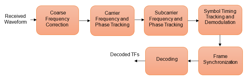
To recover the TFs from the received waveform, follow these steps.
Coarse frequency correction: Use the FFT-based algorithm to estimate the frequency offset.
Carrier frequency and phase tracking: Use the second order phase locked loop (PLL) [1] for carrier tracking.
Subcarrier frequency and phase tracking: Use the second order Costas loop [1] for subcarrier tracking.
Symbol timing tracking and demodulation: Use the second-order data transition tracking loop (DTTL) [3] module for timing synchronization and symbol demodulation [1].
Frame synchronization and decoding: Use a hard symbol based algorithm for Bose Chaudhuri Hocquenghem (BCH) code and soft symbol based algorithm for low density parity check (LDPC) code.
This figure shows the processing steps that are involved in frame synchronization and the decoding of TFs [4].
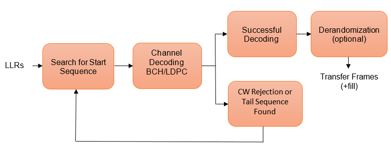
Search for start sequence: When the channel coding is BCH, the incoming bit stream is searched bit by bit for the start sequence pattern. When the channel coding is LDPC, the incoming soft symbols stream is searched with a soft correlator for the start sequence pattern. For BCH, the permissible number of errors in the start sequence is 0 or 1 (depending on the decoding mode). In error detecting mode, the permissible number of errors in the start sequence is 0. In error correcting mode, the permissible number of errors in the start sequence is 1.
Decoding: When a start sequence is detected, the decoding operation begins. The codewords (CWs) are decoded and optionally derandomized.
CW rejection or tail sequence detection: If the decoder has any decoding failure or any uncorrected errors in the decoded output, data from this failed CW is not transferred to the data link sublayer operations. The CW is rejected, and the search for the start sequence restarts. If a tail sequence is present, search for the tail sequence to detect the end of the CLTU. For BCH decoding, the CW rejection method is employed. For LDPC, use the tail sequence correlation or the CW rejection. When no tail sequence is used, the search for the start sequence must resume at the beginning of the uncorrected CW. When a tail sequence is used, the search can resume at the end of the uncorrected CW.
Simulation Configuration
Configure the number of samples per symbol and symbol rate.
% Samples per symbol
% Due to the low symbol rate and 200 KHz frequency offset, a large value of
% 200 samples per symbol must be used as a default value with
% PCM/PSK/PM modulation. For BPSK and PCM/PM/biphase-L modulation, a
% default value of 20 samples per symbol is used (due to medium and high
% symbol rates).
sps = 20;
% Symbol rate
% The symbol rates specified in TC for each modulation are:
% - For PCM/PSK/PM modulation, the coded symbol rates are 4000, 2000, 1000,
%   500, 250, 125, 62.5, 31.25, 15.625, or 7.8125 symbols/s (as specified in
%   CCSDS TC recommendation [6]).
% - For PCM/PM/biphase-L modulation, the coded symbol rates are 8000, 16000,
%   32000, 64000, 128000, or 256000 symbols/s.
% - For BPSK modulation, the coded symbol rates are 1000, 2000, 4000, 8000,
%   16000, 32000, 64000, 128000, 256000, 512000, 1024000, or 2048000
%   symbols/s.
symbolRate = 2048000;
The DTTL for the symbol synchronization performs better with an even number of samples per symbol. For an odd number of samples per symbol, the timing error estimate is nonzero at the perfect tracking of timing offset. The nonzero timing error drags the DTTL away from the perfect tracking condition.
Configure and display the CCSDS TC transmission parameters.
cfg = ccsdsTCConfig;
cfg.ChannelCoding = "BCH";
cfg.Modulation = "BPSK";
cfg.ModulationIndex = 1.2; % Applicable with PCM/PSK/PM and PCM/PM/biphase-L. Supported range in this example is [0.2 1.5].
if strcmpi(cfg.Modulation,"PCM/PSK/PM")
    cfg.SymbolRate = symbolRate;
end
cfg.SamplesPerSymbol = sps
cfg =
  ccsdsTCConfig with properties:

       DataFormat: "CLTU"
    ChannelCoding: "BCH"
    HasRandomizer: 1
       Modulation: "BPSK"
Configure the receiver parameters.
normLoopBWCarrier = 0.005;      % Normalized loop bandwidth for carrier synchronizer
normLoopBWSubcarrier = 0.00005; % Normalized loop bandwidth for subcarrier synchronizer
normLoopBWSymbol = 0.005;       % Normalized loop bandwidth for symbol synchronizer
To reduce noise contribution in the loop, decrease the loop bandwidth. The pull-in range of the frequency offset is also reduced because of decrement in the loop bandwidth. When you use a small loop bandwidth in the synchronization modules, the acquisition takes a longer time to converge. To improve the performance at low SNRs, reduce the loop bandwidth and use a higher value for the acquisition sequence length. If the loops do not track the offsets, consider increasing the loop bandwidth to increase the pull-in range.
Simulation Parameters
This example executes two burst transmissions for a number of energy per symbol to noise power spectral density ratio (Es/No) points. Es/No can be a vector or a scalar. For statistically valid BER results, run the simulation for at least 1000 number of transmissions.
numBurst  = 2;                  % Number of burst transmissions
EsNodB = [8 8.5];               % Es/No in dB
SNRIn = EsNodB - 10*log10(sps); % SNR in dB from Es/No
Processing Chain
The distorted CCSDS TC waveform with acquisition sequence and a single CLTU is processed at a time. To synchronize the received data and recover the TFs, these processing steps occur.
Generate the bits in the TC TF.
Generate the TC waveform for the acquisition sequence with alternating ones and zeros.
Generate the CCSDS TC waveform for the TFs with random bits.
Apply pulse shaping using a square root raised cosine filter (applicable only with BPSK modulation).
Apply the subcarrier frequency and phase offset (applicable only with PCM/PSK/PM modulation).
Apply the carrier frequency and phase offset.
Apply the timing phase offset.
Pass the transmitted signal through an AWGN channel.
Correct the coarse frequency and phase offset.
Filter the received signal.
Correct the carrier frequency and phase offset.
Correct the subcarrier frequency and phase offset (applicable only with PCM/PSK/PM modulation).
Correct the timing offset and symbol demodulation.
Detect the start of CLTU and decode the TFs.
% Initialization of variables to store BER and number of CLTUs lost
bitsErr = zeros(length(SNRIn),1);
cltuErr = zeros(length(SNRIn),1);

% Square root raised cosine (SRRC) transmit and receive filter objects for BPSK
if strcmpi(cfg.Modulation,"BPSK")
    % SRRC transmit filter object
    txfilter = comm.RaisedCosineTransmitFilter;
    txfilter.RolloffFactor = 0.35;    % Filter rolloff
    txfilter.FilterSpanInSymbols = 6; % Filter span
    txfilter.OutputSamplesPerSymbol = sps;
    % SRRC receive filter object
    rxfilter = comm.RaisedCosineReceiveFilter;
    rxfilter.RolloffFactor = 0.35;    % Filter rolloff
    rxfilter.FilterSpanInSymbols = 6; % Filter span
    rxfilter.DecimationFactor = 1;
    rxfilter.InputSamplesPerSymbol = sps;
end

% Sample rate
if strcmpi(cfg.Modulation,"PCM/PM/biphase-L")
    % In CCSDS TC recommendation [6] section 2.2.7, coded symbol rates are
    % defined prior to biphase-L encoding.
    fs = 2*sps*symbolRate; % Biphase-L encoding has 2 symbols for each bit
else
    fs = sps*symbolRate;
end

for iSNR = 1:length(SNRIn)

    % Set the random number generator to default
    rng default

    % SNR value in the loop
    SNRdB = SNRIn(iSNR);

    % Initialization of error computing parameters
    totNumErrs = 0;
    numErr = 0;
    totNumBits = 0;
    cltuLost = 0;

    for iBurst = 1:numBurst

        % Acquisition sequence with 800 octets
        acqSeqLength = 6400;
        acqBits = repmat([0;1], 0.5*acqSeqLength, 1); % Alternating ones and zeros with zero as starting bit, starting bit can be either zero or one

        % CCSDS TC Waveform for acquisition sequence
        % Maximum subcarrier frequency offset specified in CCSDS TC is
        % ±(2*1e-4)*fsc, where fsc is the subcarrier frequency
        subFreqOffset = 3.2; % Subcarrier frequency offset in Hz
        subPhaseOffset = 4;  % Subcarrier phase offset in degrees
        % Frequency offset in Hz
        if strcmpi(cfg.Modulation,'PCM/PSK/PM')
            % Signal modulation along with subcarrier frequency and phase offset
            acqSymb = HelperCCSDSTCSubCarrierModulation(acqBits,cfg,subFreqOffset,subPhaseOffset);
        else
            % Signal modulation as per the specified scheme in CCSDS telecommmand
            % Subcarrier impairments are not applicable with BPSK and PCM/PM/biphase-L
            cfg.DataFormat = 'acquisition sequence';
            acqSymb = ccsdsTCWaveform(acqBits,cfg);
            cfg.DataFormat = 'CLTU';
        end

        % CCSDS TC waveform for CLTU
        transferFramesLength = 640;                   % Number of octets in the transfer frame
        inBits = randi([0 1],transferFramesLength,1); % Bits in the TC transfer frame
        if strcmpi(cfg.Modulation,'PCM/PSK/PM')
            % Encoded bits after TC synchronization and channel coding sublayer operations
            [~,encBits] = ccsdsTCWaveform(inBits,cfg);
            % Signal modulation along with subcarrier frequency and phase offset
            waveSymb = HelperCCSDSTCSubCarrierModulation(encBits,cfg,subFreqOffset,subPhaseOffset);
        else
            waveSymb = ccsdsTCWaveform(inBits,cfg);
        end

        % CCSDS TC waveform with acquisition sequence and CLTU
        waveform = [acqSymb;waveSymb];

        % Transmit filtering for BPSK
        if strcmpi(cfg.Modulation,'BPSK')
            % Pulse shaping using SRRC filter
            data = [waveform;zeros(txfilter.FilterSpanInSymbols,1)];
            txSig = txfilter(data);
        else
            txSig = waveform;
        end

        % Add carrier frequency and phase offset
        freqOffset = 200000;  % Frequency offset in Hz
        phaseOffset = 20;     % Phase offset in degrees
        if fs <= (2*(freqOffset+cfg.SubcarrierFrequency)) && strcmpi(cfg.Modulation,'PCM/PSK/PM')
            error('Sample rate must be greater than twice the sum of frequency offset and subcarrier frequency');
        elseif fs <= (2*freqOffset)
            error('Sample rate must be greater than twice the frequency offset');
        end
        pfo = comm.PhaseFrequencyOffset('FrequencyOffset',freqOffset, ...
            'PhaseOffset',phaseOffset,'SampleRate',fs);
        txSigOffset = pfo(txSig);

        % Timing offset as an integer number of samples
        timingErr = 5;        % Timing error must be <= 0.4*sps
        delayedSig  = [zeros(timingErr,1);txSigOffset];

        % Pass the signal through an AWGN channel
        rxSig = awgn(complex(delayedSig),SNRdB,'measured',iBurst);

        % Coarse carrier frequency synchronization
        if strcmpi(cfg.Modulation,'PCM/PSK/PM')
             % Coarse carrier frequency synchronization for PCM/PSK/PM
            coarseSync = HelperCCSDSTCCoarseFrequencyCompensator('FrequencyResolution',100,...
                'SampleRate',fs);
        else
            % Coarse carrier frequency synchronization for BPSK and PCM/PSK/biphase-L
            coarseSync = comm.CoarseFrequencyCompensator( ...
                'Modulation','BPSK','FrequencyResolution',100, ...
                'SampleRate',fs);
        end

        % Compensation for coarse frequency offset
        [rxCoarse,estCoarseFreqOffset] = coarseSync(rxSig);

        % Receive filtering
        if strcmpi(cfg.Modulation,'BPSK')
            % SRRC receive filtering for BPSK
            rxFiltDelayed = rxfilter(rxCoarse);
            rxFilt = rxFiltDelayed(rxfilter.FilterSpanInSymbols*sps+1:end);
        else
            % Low-pass filtering for PCM/PSK/PM and PCM/PSK/biphase-L
            % Filtering is done with a lowpass filter to reduce the effect of
            % noise to the carrier phase tracking loop
            b = fir1(40,0.3); % Coefficients for 40th-order lowpass filter with cutoff frequency = 0.3*fs/2
            rxFiltDelayed = filter(b,1,[rxCoarse;zeros(0.5*(length(b)-1),1)]);
            % Removal of filter delay
            rxFilt = rxFiltDelayed(0.5*(length(b)-1)+1:end);
        end

        % Fine frequency and phase correction
        if strcmpi(cfg.Modulation,'BPSK')
            fineSync = comm.CarrierSynchronizer('SamplesPerSymbol',sps, ...
                'Modulation','BPSK','NormalizedLoopBandwidth',normLoopBWCarrier);
        else
            fineSync = HelperCCSDSTCCarrierSynchronizer('SamplesPerSymbol', ...
                cfg.SamplesPerSymbol,'NormalizedLoopBandwidth',normLoopBWCarrier);
        end
        [rxFine,phErr] = fineSync(rxFilt);

        % Subcarrier frequency and phase correction
        if strcmpi(cfg.Modulation,'PCM/PSK/PM')
            subSync = HelperCCSDSTCSubCarrierSynchronizer('SamplesPerSymbol',sps, ...
                'NormalizedLoopBandwidth',normLoopBWSubcarrier);
            [rxSub,subCarPhErr] = subSync(real(rxFine));
        else
            rxSub = real(rxFine);
        end

        % Timing synchronization and symbol demodulation
        timeSync = HelperCCSDSTCSymbolSynchronizer('SamplesPerSymbol',sps, ...
            'NormalizedLoopBandwidth',normLoopBWSymbol);
        [rxSym,timingErr] = timeSync(rxSub);

        % Search for start sequence and bit recovery
        bits = HelperCCSDSTCCLTUBitRecover(rxSym,cfg,'Error Correcting',0.8);
        bits = bits(~cellfun('isempty',bits)); % Removal of empty cell array contents

        % Length of transfer frames with fill bits
        if strcmpi(cfg.ChannelCoding,'BCH')
            messageLength = 56;
        else
            messageLength = 0.5*cfg.LDPCCodewordLength;
        end
        frameLength = messageLength*ceil(length(inBits)/messageLength);

        if (isempty(bits)) || (length(bits{1})~= frameLength) ||(length(bits)>1)
            cltuLost = cltuLost + 1;
        else
            numErr = sum(abs(double(bits{1}(1:length(inBits)))-inBits));
            totNumErrs = totNumErrs + numErr;
            totNumBits = totNumBits + length(inBits);
        end
    end
    bitsErr(iSNR) = totNumErrs/totNumBits;
    cltuErr(iSNR) = cltuLost;

    % Display of bit error rate and number of CLTUs lost
    fprintf([['\nBER with ', num2str(SNRdB+10*log10(sps)) ],' dB Es/No : %1.2e\n'],bitsErr(iSNR));
    fprintf([['\nNumber of CLTUs lost with ', num2str(SNRdB+10*log10(sps)) ],' dB Es/No : %d\n'],cltuErr(iSNR));
end
BER with 8 dB Es/No : 0.00e+00
Number of CLTUs lost with 8 dB Es/No : 0
BER with 8.5 dB Es/No : 0.00e+00
Number of CLTUs lost with 8.5 dB Es/No : 0
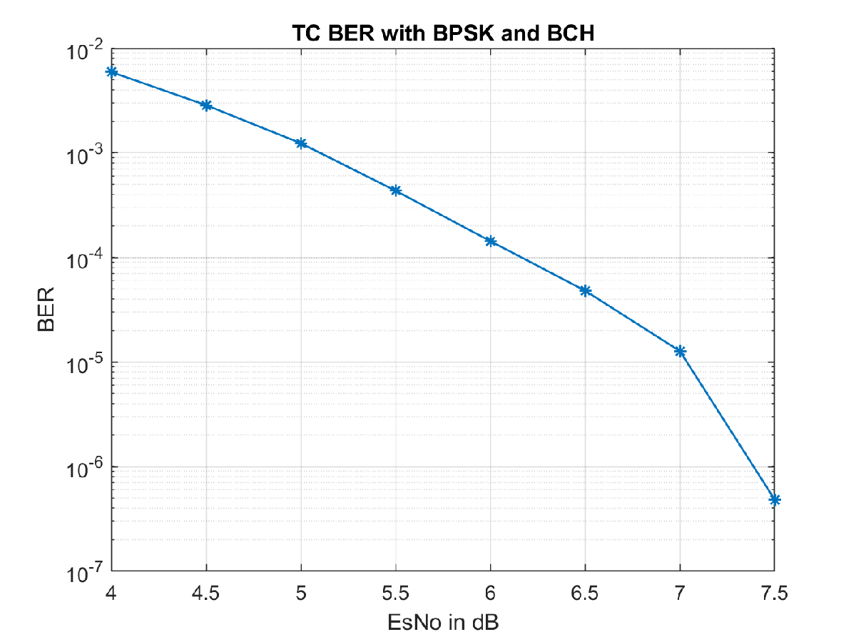
BER Results
When each Es/No point is completed, the BER results for the simulation are plotted. bitsErr is an array with the measured BER for all simulated Es/No points. The figure shows the simulation result that are obtained with 10,000 number of transmissions and Es/No points in the range [4 7.5].
Further Exploration
Normalized Loop Bandwidth and Acquisition Sequence Length
This example uses a large value for the acquisition sequence length (800 octets) to improve the performance of synchronizers at low SNR values. This table shows the normalized loop bandwidth values and the samples per symbol used in the simulation with each modulation scheme, for an acquisition sequence of 800 octets.
T = table({'BPSK';'PCM/PSK/PM';'PCM/PM/biphase-L'},[0.005; 0.0002; 0.0003], ...
          {'Not Applicable';0.00005;'Not Applicable'},[0.005; 0.0005; 0.0005], ...
          [20; 200; 20],[2048000; 4000; 256000],'VariableNames',{'Modulation','Carrier Synchronizer',...
'Subcarrier Synchronizer','Symbol Synchronizer','Samples per symbol','Symbol rate'})T=3×6 table
Modulation Carrier Synchronizer Subcarrier Synchronizer Symbol Synchronizer Samples per symbol Symbol rate
____________________ ____________________ _______________________ ___________________ __________________ ___________
{'BPSK' } 0.005 {'Not Applicable'} 0.005 20 2.048e+06
{'PCM/PSK/PM' } 0.0002 {[ 5.0000e-05]} 0.0005 200 4000
{'PCM/PM/biphase-L'} 0.0003 {'Not Applicable'} 0.0005 20 2.56e+05
You can use this example to further explore these synchronization modules.
Carrier synchronization: To improve the accuracy of the phase estimate, you can reduce the noise contribution to the tracking loops by decreasing the normalized bandwidth. Reducing the loop bandwidth reduces the pull-in range, and the acquisition takes a longer time to converge.
Subcarrier synchronization: You can plot the estimated subcarrier offset to identify a more accurate loop bandwidth. To help improve the accuracy of the subcarrier frequency estimate, you can increase the sample rate and SNR.
Symbol synchronization: The DTTL for the symbol synchronization performs well at higher number of samples per symbol. As you increase the samples per symbol, the resolution increases, and the DTTL performance improves. Too many samples per symbol can reduce the SNR and affect the performance. If the SNR is less than –15 dB (due to a large number of samples per symbol), the performance of the tracking loops is affected.
For any PLL-based loop, to operate at very low SNR, the loop bandwidth must be very low. This low loop bandwidth reduces the pull-in range. For the CLTUs with LDPC channel coding, if the number of CLTUs lost is high, you can reduce the threshold value for the detection of the start sequence in the helper function HelperCCSDSTCCLTUBitRecover. You can also try improving the BER results by selecting only the CLTUs with a very high normalized correlation metric with the start sequence. To maximize the frame detection and minimize the false alarm, 0.8 is used as a detection threshold in this example. To reduce the false alarm, you can increase the detection threshold value. If you increase the detection threshold value, the frame detection rate reduces.
Subcarrier Frequency Offset with PCM/PSK/PM
The maximum subcarrier frequency offset specified in the CCSDS TC recommendation [6] is , where is the frequency of telecommand subcarrier. You must consider a frequency offset maximum of 3.2 Hz or 1.6 Hz with a 16 KHz or 8 KHz sine wave subcarrier, respectively. You can plot the estimated subcarrier frequency offset to analyze the performance of the subcarrier tracking. When the synchronizer converges, the mean value of the estimate is approximately equal to the input subcarrier frequency offset value of 3.2 Hz.
if strcmpi(cfg.Modulation,'PCM/PSK/PM')
    estSubCarFreqOffset = diff(subCarPhErr)*fs/(2*pi);
    rmean = cumsum(estSubCarFreqOffset)./(1:length(estSubCarFreqOffset))';
    plot(rmean)
    xlabel('Symbols')
    ylabel('Estimated Subcarrier Frequency Offset (Hz)')
    title('PCM/PSK/PM: Subcarrier Frequency Offset')
    grid on
end
Appendix
The example uses these helper functions:
HelperCCSDSTCCoarseFrequencyCompensator: Perform coarse carrier frequency synchronization
HelperCCSDSTCCarrierSynchronizer: Perform fine carrier synchronization
HelperCCSDSTCSubCarrierSynchronizer: Perform subcarrier synchronization
HelperCCSDSTCSymbolSynchronizer: Perform symbol timing synchronization and demodulation
HelperCCSDSTCSubCarrierModulation: Perform subcarrier modulation with frequency and phase offset
HelperCCSDSTCCLTUBitRecover: Search for start sequence and bit recovery
Bibliography
J. Vilà-Valls, M. Navarro, P. Closas and M. Bertinelli, "Synchronization challenges in deep space communications," IEEE Aerospace and Electronic Systems Magazine, vol. 34, no. 1, pp. 16-27, Jan. 2019.
M. Baldi et al., "State-of-the-art space mission telecommand receivers," IEEE Aerospace and Electronic Systems Magazine, vol. 32, no. 6, pp. 4-15, June 2017.
S. Million and S. Hinedi, "Effects of symbol transition density on the performance of the data transition tracking loop at low signal-to-noise ratios," Proceedings IEEE International Conference on Communications ICC '95, Seattle, WA, USA, 1995, pp. 1036-1040 vol.2.
TC Synchronization and Channel Coding. Recommendation for Space Data System Standards, CCSDS 231.0-B-3. Blue Book. Issue 3. Washington, D.C.:CCSDS, September 2017.
TC Synchronization and Channel Coding. Summary of Concept and Rationale. CCSDS 230.1-G-2. Green Book. Issue 2. Washington, D.C.: CCSDS, November 2012.
Radio Frequency and Modulation Systems - Part 1. Earth Stations and Spacecraft. CCSDS 401.0-B-29. Blue Book. Issue 29. Washington, D.C.: CCSDS, March 2019.
Michael Rice, Digital Communications - A Discrete-Time Approach. New York: Prentice Hall, 2008.
Nguyen, T.M., W.L. Martin, and Hen-Geul Yeh. "Required Bandwidth, Unwanted Emission, and Data Power Efficiency for Residual and Suppressed Carrier Systems-a Comparative Study." IEEE transactions on electromagnetic compatibility 37, no. 1 (February 1995): 34-50. https://doi.org/10.1109/15.350238.