End-to-End CCSDS Flexible Advanced Coding and Modulation Simulation with RF Impairments and Corrections
This example shows how to measure the bit error rate (BER) of the end-to-end chain of the Consultative Committee for Space Data Systems (CCSDS) flexible advanced coding and modulation (FACM) scheme for high rate telemetry (TM) applications system [1].
Introduction
Data from various instruments is generated in the satellite. This data collectively is called TM data. Earth exploration satellite service (EESS) missions carry payloads that produce substantial TM data rates, starting from a few hundreds of Mbps. To achieve high spectral efficiency for such missions, coding and modulation schemes must be adjusted based on the link budget. The CCSDS FACM scheme for high rate TM applications [1] standard supports a high data rate by adopting the serial concatenated convolutional codes (SCCC) and modulation schemes from the family of phase shift keying (PSK) and amplitude phase shift keying (APSK). This example shows how to generate a complex baseband CCSDS FACM waveform from the randomly generated transfer frames (TFs), introduce radio frequency (RF) impairments to the baseband signal, and add additive white Gaussian noise (AWGN) to the impaired signal. Then, the example shows the symbol timing recovery, carrier frequency synchronization, demodulation, and decoding of this impaired noisy signal to get the final bits in the form of TFs. This example also shows how to measure the BER with respect to the signal-to-noise ratio (SNR) for one configuration of the CCSDS FACM signal.
This example models these RF impairments on the baseband signal:
Carrier frequency offset (CFO)
Doppler rate
Sampling rate offset (SRO)
Phase noise
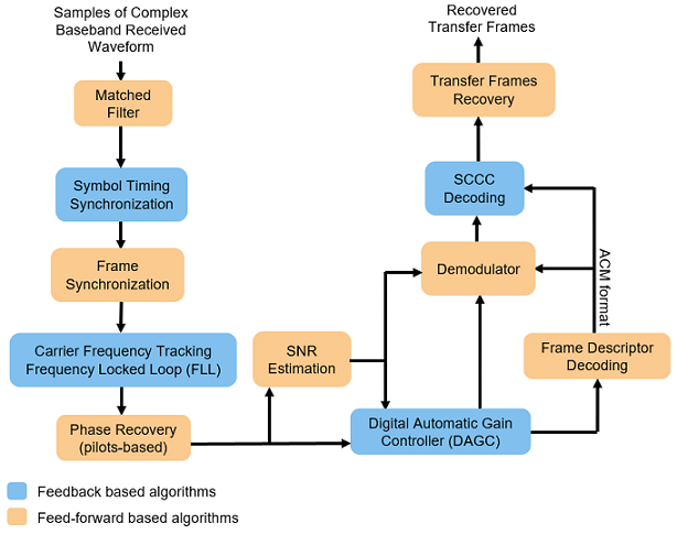
This figure shows the receiver process, which recovers the symbol timing, carrier frequency, and carrier phase in the presence of the RF impairments.

In the receiver chain, frequency locked loop (FLL) uses the frame marker (FM) that is available in the physical layer (PL) header. The phase recovery module uses the pilot fields to recover the phase. Because the phase recovery algorithm is pilots-based, you must enable the pilot fields for the example to work. The phase recovery module can tolerate some amount of residual CFO that is left after the FLL operation.
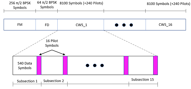
This figure shows the PL frame structure of the FACM waveform. In one PL frame, 16 code word sections (CWS) exist and each codeword section is formed from each SCCC encoder output. Use the ccsdsTMWaveformGenerator System object to generate the FACM waveform.

Configuration and Simulation Parameters
This example shows various visualizations such as constellation plots and the spectrum of the signal. You can optionally disable these visualizations. For this example, enable them.
showVisualizations =  true;
true;Set the configuration parameters that control the waveform properties.
sps = 2;                                    % Samples per symbol (SPS)
rolloff = 0.35;                             % Filter roll-off factor
cfgCCSDSFACM.NumBytesInTransferFrame = 223;
cfgCCSDSFACM.SamplesPerSymbol = sps;
cfgCCSDSFACM.RolloffFactor = rolloff;
cfgCCSDSFACM.FilterSpanInSymbols = 10;
cfgCCSDSFACM.ScramblingCodeNumber = 1;
cfgCCSDSFACM.ACMFormat = 1;
cfgCCSDSFACM.HasPilots = true;              % HasPilots must be set to true
                                            % for this example to work
Specify the simulation parameters in simParams structure. Specify the SNR in dB as energy per symbol to noise power ratio (Es/No) in the EsNodB field.
simParams.EsNodB = 1;
Specify the CFO and SRO. Model CFO using the comm.PhaseFrequencyOffset System object. Model the sampling rate offset is using the comm.SampleRateOffset System object.
simParams.CFO = 1e6; % In Hz
simParams.SRO = 20;  % In PPM
Specify the attenuation factor for the signal. In the case of no attenuation, specify this value as 1.
simParams.AttenuationFactor = 0.1; % Must be less than or equal to 1Specify the number of PL frames to be generated by specifying the number of frames for initial synchronization that are not accounted in the BER calculation and the number of frames that are accounted in the BER calculations. In this example, set simParams.NumFramesForBER to 10 to complete the simulation early. To see a proper BER value, set this value to 200.
% Initialize the number of frames used for synchronization
simParams.InitalSyncFrames = 15;
% Initialize the number of frames that are used for calculation of BER
simParams.NumFramesForBER = 10;
simParams.NumPLFrames = simParams.InitalSyncFrames + simParams.NumFramesForBER;
Specify the symbol rate and samples per symbol (SPS).
simParams.SymbolRate = 100e6; % 100 MBaud
simParams.SPS = sps;
Calculate Latency and Doppler in a Satellite Scenario example shows how the Doppler shift changes with time based on the satellite orbit. The Doppler shift follows a sinusoidal curve with the peak Doppler shift occurring when the satellite starts to become visible to a receiver on the ground, or when the satellite is receding. Such a cyclic change in Doppler shift is modeled as a sinusoidal Doppler profile. The current example simulates Doppler frequency that changes as given in this equation from [2].
is the peak Doppler shift, and is the Doppler rate. Specify these properties of the Doppler profile.
simParams.PeakDoppler = 1e6;  % In Hz
simParams.DopplerRate = 50e3; % In Hz/Sec
If needed, disable RF impairments for debugging.
simParams.DisableRFImpairments = false; % Disable RF impairmentsGeneration of CCSDS FACM Waveform Distorted with RF Impairments
To create a CCSDS FACM waveform, use the HelperCCSDSFACMRxInputGenerate helper function, with the simParams and cfgCCSDSFACM structures as inputs. This function uses the ccsdsTMWaveformGenerator System object to generate the transmitted waveform. This function returns the data signal, transmitted and received waveforms, and receiver processing structure. The received waveform is impaired with carrier frequency, Doppler shift, timing phase offsets, and phase noise and then passed through an AWGN channel. The receiver processing parameters structure, rxParams, includes the reference pilot fields and pilot indices. Plot the constellation of the received symbols and the spectrum of the transmitted and received waveforms.
[bits,txOut,rxIn,phyParams,rxParams] = ...
    HelperCCSDSFACMRxInputGenerate(cfgCCSDSFACM,simParams);

if showVisualizations == true

    % Plot the received signal constellation
    rxConst = comm.ConstellationDiagram(Title = "Received data", ...
        XLimits = [-1 1], YLimits = [-1 1], ...
        ShowReferenceConstellation = true, ...
        SamplesPerSymbol = simParams.SPS);

    % Calculate the reference constellation for the specified ACM format.
    refConstellation = HelperCCSDSFACMReferenceConstellation(cfgCCSDSFACM.ACMFormat);
    rxConst.ReferenceConstellation = refConstellation;
    rxConst(rxIn(1:rxParams.plFrameSize*sps))

    % Plot the transmitted and received signal spectrum
    Fsamp = simParams.SymbolRate*simParams.SPS;
    scope = spectrumAnalyzer(SampleRate=Fsamp, ...
        ChannelNames = ["Transmitted waveform" "Received waveform"], ...
        ShowLegend = true);
    scope([txOut,rxIn(1:length(txOut))]);
end


Configuration of the Receiver
Create a square root raised cosine (SRRC) receive filter.
rxFilterDecimationFactor = sps/2;
rrcfilt = comm.RaisedCosineReceiveFilter( ...
    RolloffFactor = double(rolloff), ...
    FilterSpanInSymbols = double(cfgCCSDSFACM.FilterSpanInSymbols), ...
    InputSamplesPerSymbol = sps, ...
    DecimationFactor = rxFilterDecimationFactor);
b = coeffs(rrcfilt);

% |H(f)| = 1  for |f| < fN(1-alpha), as per Section 6 in the standard [1]
rrcfilt.Gain = sum(b.Numerator);
Create a symbol timing synchronization System object, comm.SymbolSynchronizer.
% Initialize the detector gain. See Eq 8.47 in Digital communications by
% Michael Rice [3].
Kp = 1/(pi*(1-((rolloff^2)/4)))*sin(pi*rolloff/2);
symsyncobj = comm.SymbolSynchronizer( ...
    DampingFactor = 1/sqrt(2), ...
    DetectorGain = Kp, ...
    TimingErrorDetector = "Gardner (non-data-aided)", ...
    Modulation = "PAM/PSK/QAM", ...
    NormalizedLoopBandwidth = 0.0001, ...
    SamplesPerSymbol = sps/rxFilterDecimationFactor);
Visualize the constellation plot after timing and frequency recovery by creating a comm.ConstellationDiagram System object.
if showVisualizations == true
    constelDiag = comm.ConstellationDiagram( ...
        Title = "Constellation after Timing and Frequency Synchronization");
    constelDiag.ReferenceConstellation = refConstellation;
end
Initialize the FLL for carrier frequency synchronization. This figure shows the FLL implementation, as described in section 5.7 in [2]. In this case, the frequency detector is implemented with a fast Fourier transform (FFT) based approach, where the peak in frequency domain indicates the residual carrier frequency. Because this approach is limited by the resolution of the FFT, interpolate around the peak in the frequency domain to detect the residual frequency. Because this approach uses the FM that is available in the PL header, complete the frame synchronization before passing the signal through the FLL. This figure shows the type-2 FLL that handles large Doppler rates.

Initialize the FLL. When you set K2 to 0, this FLL becomes a type-1 FLL.
fll = HelperCCSDSFACMFLL(SampleRate = simParams.SymbolRate, ...
    K1 = 0.17, K2 = 0);
Initialize local variables for the receiver chain to work.
plFrameSize = rxParams.plFrameSize;
stIdx = 0;                          % PL frame starting index

% Use one PL frame for each iteration.
endIdx = stIdx + plFrameSize*sps;
rxParams.ffBuffer = complex(zeros(plFrameSize,1));
Synchronization and Data Recovery
To recover the data from the received signal, follow these steps.
Pass the received baseband samples through the SRRC receive filter.
Perform symbol timing synchronization. use the
comm.SymbolSynchronizerSystem object for symbol timing synchronization. The SRO is compensated while performing symbol timing synchronization.Apply frame synchronization to detect the frame boundaries.
Pass the frame synchronized symbols through the FLL. In the FLL, along with the CFO, the Doppler rate and Doppler shift are also tracked.
Estimate and compensate the remaining frequency offset in the FM using the reference FM.
Recover the residual phase from the phase recovery module. The phase recovery module can tolerate some residual CFO.
Estimate the SNR in the signal by using the phase compensated FM.
Pass the phase compensated signal through the digital automatic gain controller (DAGC).
Demodulate the synchronized symbols to get soft bits.
Perform SCCC decoding on the soft bits to obtain the decoded bits. SCCC decoding can be done using a-posteriori probability (APP) decoder System object,
comm.APPDecoder.Recover the transfer frames from the decoded bits.
This figure shows the SCCC decoder block diagram.

% Initialize the number of symbols in a code block. Assuming pilots are
% present in the signal, 15*16 pilots and 8100 data symbols exist in one
% code block.
n = 8100 + 15*16;

% Perform frame synchronization for the first frame outside the loop.

% In the last frame, consider all of the remaining samples in the received
% waveform.
isLastFrame = endIdx > length(rxIn);
endIdx(isLastFrame) = length(rxIn);
rxData = rxIn(stIdx+1:endIdx);
stIdx = endIdx; % Update start index after extracting required data

filteredRx = rrcfilt(rxData);     % RRC filter
syncsym = symsyncobj(filteredRx); % Symbol timing synchronization

% Frame synchronization
syncidx = HelperCCSDSFACMFrameSync(syncsym,rxParams.RefFM);
fineCFOSync = comm.PhaseFrequencyOffset(SampleRate = simParams.SymbolRate);

leftOutSym = syncsym(syncidx(1):end);
extraBits = [];
numIterations = 10;
frameIndex = 1;
berinfo = struct("NumBitsInError",0, ...
    "TotalNumBits",0, ...
    "BitErrorRate",0);
snrAveragingFactor = 6; % Average over 6 frames to get accurate estimate of SNR
SNREst = zeros(snrAveragingFactor,1);
idxTemp = 0;
G = 1;
numFramesLost = 0;
fqyoffset = zeros(1000,1);
while stIdx < length(rxIn)
    isFrameLost = false;

    % Use one PL frame for each iteration.
    endIdx = stIdx + rxParams.plFrameSize*sps;

    % In the last frame, consider all of the remaining samples in the received
    % waveform.
    isLastFrame = endIdx > length(rxIn);
    endIdx(isLastFrame) = length(rxIn);
    rxData = rxIn(stIdx+1:endIdx);
    stIdx = endIdx; % Update start index after extracting required data
    if ~isLastFrame
        % Filter the received data
        filteredRx = rrcfilt(rxData); % RRC filter

        % Synchronize the symbol timing
        syncsym = symsyncobj(filteredRx);

        % Synchronize the data to the frame boundaries
        syncidx = HelperCCSDSFACMFrameSync(syncsym,rxParams.RefFM);

        % Consider one complete PL frame beginning with a header. Append
        % zeros if data is not sufficient. This situation typically happens
        % when samples are lost while doing timing synchronization or when
        % synchronization is lost.
        tempSym = [leftOutSym;syncsym(1:syncidx(1)-1)];
        leftOutSym = syncsym(syncidx(1):end);
        if length(tempSym)<n*16+320 % 16 code blocks and 320 header symbols
            fllIn = [tempSym;zeros(n*16+320-length(tempSym),1)];
        else                          % length(tempSym)>=n*16 + 320
            fllIn = tempSym(1:n*16+320);
        end

        % Track the frequency offset
        [fllOut,fqyoffset(frameIndex)] = fll(fllIn);

        % Estimate and compensate the CFO from the FM.
        cfoEst = HelperCCSDSFACMFMFrequencyEstimate(fllOut(1:256), ...
            rxParams.RefFM,simParams.SymbolRate);
        fineCFOSync.FrequencyOffset = -cfoEst;
        fqysyncedFM = fineCFOSync(fllOut(1:256));

        % Estimate and compensate for the phase offset in each frame
        % independently. Remove the pilots in the process.
        [noPilotsSym,frameDescriptor] = ...
            HelperCCSDSFACMPhaseRecovery(fllOut,rxParams.PilotSeq,rxParams.RefFM);
        agcIn = [frameDescriptor;noPilotsSym];

        % Estimate the SNR. See CCSDS 130.11-G-1 Section 5.5 [2].
        SNREst(idxTemp+1) = HelperCCSDSFACMSNREstimate(fqysyncedFM(1:256), ...
            rxParams.RefFM);

        % Average the estimated SNR over multiple frames
        finalSNREst = mean(SNREst);
        idxTemp = mod(idxTemp+1,6);

        % Pass the signal through DAGC
        if frameIndex >= snrAveragingFactor
            [agcRecovered,G] = HelperDigitalAutomaticGainControl(agcIn,finalSNREst,G);
        else
            agcRecovered = agcIn;
        end

        if showVisualizations == true
            % Plot the constellation.
            constelDiag(agcRecovered(:))
        end

        % Recover the ACM format pilots availability indicator.
        [ACMFormat, hasPilots,decFail] = HelperCCSDSFACMFDRecover(agcRecovered(1:64));

        if decFail
            isFrameLost = true;
        end

        if (ACMFormat ~= cfgCCSDSFACM.ACMFormat) || (hasPilots ~= cfgCCSDSFACM.HasPilots)
            isFrameLost = true;
        end

        % Continue further processing only if the frame is not lost.
        if ~isFrameLost
            % De-randomize the PL-frame.
            derandomized = agcRecovered(65:end).*conj(rxParams.PLRandomSymbols(:));

            % Demodulate the signal
            nVar = 1/finalSNREst;
            demodulated = reshape(HelperCCSDSFACMDemodulate(derandomized,ACMFormat,nVar), ...
                [],16);

            fullFrameDecoded = zeros(16*phyParams.K,1);

            for iCodeWord = 1:16
                decoded = HelperSCCCDecode(demodulated(:,iCodeWord),ACMFormat,numIterations);
                fullFrameDecoded((iCodeWord-1)*phyParams.K+1:iCodeWord*phyParams.K) = ...
                    decoded;
            end

            % Extract TFs.
            [initBits,deccodedBuffer,extraBits] = ...
                HelperCCSDSFACMTFSynchronize([extraBits;fullFrameDecoded], ...
                phyParams.ASM, ...
                phyParams.NumInputBits);
            PRNSeq = satcom.internal.ccsds.tmrandseq(phyParams.NumInputBits);
            if ~isempty(deccodedBuffer)
                finalBits = xor(deccodedBuffer(33:end,:)>0,PRNSeq);
            else
                isFrameLost = true;
                extraBits = [];
            end
        end

        if isFrameLost
            numFramesLost = numFramesLost + 1;
        end

        % Find BER
        if frameIndex>simParams.InitalSyncFrames && ~isFrameLost
            berinfo = HelperBitErrorRate(bits,finalBits,berinfo);
            disp("frameIndex = " + frameIndex + ". BER = " + berinfo.BitErrorRate)
        end
        frameIndex = frameIndex + 1;
    end
end
frameIndex = 16. BER = 0
frameIndex = 17. BER = 0
frameIndex = 18. BER = 0
frameIndex = 19. BER = 0
frameIndex = 20. BER = 0
frameIndex = 21. BER = 0
frameIndex = 22. BER = 0
frameIndex = 23. BER = 0
frameIndex = 24. BER = 0
frameIndex = 25. BER = 0
frameIndex = 26. BER = 0
frameIndex = 27. BER = 0
frameIndex = 28. BER = 0
frameIndex = 29. BER = 0
frameIndex = 30. BER = 0

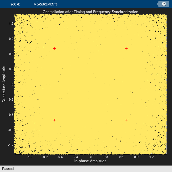
The constellation appears noisy because the default example operates at 1 dB SNR. The default example decodes 30 frames without any error at 1 dB SNR, thereby illustrating the error correction capability of serial concatenated convolutional codes.
disp("ACM format = " + cfgCCSDSFACM.ACMFormat + ". Es/No(dB) = " + ...
    simParams.EsNodB + ". BER = " + berinfo.BitErrorRate)
ACM format = 1. Es/No(dB) = 1. BER = 0
This plot shows the frequency convergence of the estimated frequency offset. This plot shows the number of frames required for the FLL to converge. The plot shows that the frequency offset converges even at a very low SNR (0 dB Es/No). This observation shows that the FLL can operate effectively at low SNR values.
if showVisualizations == true
    plot(fqyoffset(1:frameIndex-1));
    grid on
    ylabel("Estimated Frequency Offset (Hz)")
    xlabel("Number of Frames")
    title("Frequency Offset Convergence")
end

Further Exploration
This example shows the calculation of BER for one ACM format at one SNR point. Run BER simulations for multiple SNR points and multiple ACM formats.
This example uses Es/No as the SNR metric. To convert this to energy per bit to noise power ratio (Eb/No), use this code.
% ccsdsWaveGen = ccsdsTMWaveformGenerator('WaveformSource','flexible advanced coding and modulation', ...
%     'ACMFormat',cfgCCSDSFACM.ACMFormat);
% codeRate = ccsdsWaveGen.info.ActualCodeRate;
% modOrder = ccsdsWaveGen.info.NumBitsPerSymbol;
% EbNodB = simParams.EsNodB - 10*log10(codeRate) - 10*log10(modOrder);
Appendix
The example uses these helper files:
HelperBitErrorRate.m - Calculate bit error rate
HelperCCSDSFACMDemodulate.m - Demodulate the received FACM signal
HelperCCSDSFACMFDRecover.m - Recover frame descriptor
HelperCCSDSFACMFLL.m - FLL for carrier frequency recovery
HelperCCSDSFACMFMFrequencyEstimate.m - Estimate frequency offset in FM
HelperCCSDSFACMFrameMarker.m - Generate reference FM
HelperCCSDSFACMFrameSync.m - Estimate frame beginning
HelperCCSDSFACMPhaseRecovery.m - Recover phase in the signal
HelperCCSDSFACMReferenceConstellation.m - Generate reference constellation for a given ACM format
HelperCCSDSFACMRxInputGenerate.m - Generate transmitter waveform, model RF impairments, and add AWGN
HelperCCSDSFACMSNREstimate.m - Estimate SNR in received signal
HelperCCSDSFACMTFSynchronize.m - Transfer frame synchronization
HelperDigitalAutomaticGainControl.m - Digital automatic gain control
HelperDopplerShift.m - Model sinusoidal Doppler profile
HelperSCCCDecode.m - Iterative decoder for SCCC
References
[1] CCSDS 131.2-B-1. Blue Book. Issue 1. "Flexible Advanced Coding and Modulation Scheme for High Rate Telemetry Applications." Recommendation for Space Data System Standards. Washington, D.C.: CCSDS, March 2012.
[2] CCSDS 130.11-G-1. Green Book. Issue 1. "SCCC—Summary of Definition and Performance." Informational Report Concerning Space Data System Standards. Washington, D.C.: CCSDS, April 2019.
[3] Rice, Michael. Digital Communications: A Discrete-Time Approach. Pearson/Prentice Hall, 2008.