Planetary Gear
Gear train with sun, planet, and ring gears
Libraries:
Simscape /
Driveline /
Gears
Description
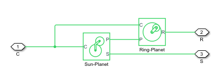
The Planetary Gear block models a gear train with sun, planet, and ring gears. Planetary gears are common in transmission systems, where they provide high gear ratios in compact geometries. A carrier connected to a drive shaft holds the planet gears. Ports C, R, and S represent the shafts connected to the planet gear carrier, ring gear, and sun gear.

The block models the planetary gear as a structural component based on Sun-Planet and Ring-Planet Simscape™ Driveline™ blocks. The figure shows the block diagram of this structural component.

To increase the fidelity of the gear model, you can specify properties such as gear inertia, meshing losses, and viscous losses. By default, gear inertia and viscous losses are assumed to be negligible.
Thermal Model
You can model
the effects of heat flow and temperature change by enabling the optional thermal port. To enable
the port, set Friction model to Temperature-dependent
efficiency.
Equations
The Planetary Gear block imposes two kinematic and two geometric constraints,
where:
rC is the radius of the carrier gear.
ωC is the angular velocity of the carrier gear.
rS is the radius of the sun gear.
ωS is the angular velocity of the sun gear.
rP is the radius of planet gear.
ωp is the angular velocity of the planet gears.
rR is the radius of the ring gear.
The ring-sun gear ratio is
where N is the number of teeth on each gear.
In terms of this ratio, the key kinematic constraint is:
The four degrees of freedom reduce to two independent degrees of freedom. The gear pairs are (1, 2) = (S, P) and (P, R).
Warning
The gear ratio gRS must be strictly greater than one.
The torque transfer is
where:
τS is torque transfer for the sun gear.
τR is torque transfer for the ring gear.
τloss is torque transfer loss.
In the ideal case where there is no torque loss, τloss = 0.
In the nonideal case, τloss ≠ 0. For more information, see Model Gears with Losses.
Assumptions and Limitations
Gear inertia is assumed to be negligible.
Gears are treated as rigid components.
Coulomb friction slows down simulation. For more information, see Adjust Model Fidelity.
