Drivetrain Model
What the Model Represents
The CR-CR Four-Speed Transmission example model simulates a complete drivetrain. This example helps you understand how to model driveline components with Simscape™ Driveline™ blocks, connect them into a realistic model, use Simulink® blocks and variant subsystems in driveline modeling, and simulate and modify a drivetrain model.
This driveline mechanism is part of a full vehicle, without the engine or engine-drivetrain coupling, and without the final differential and wheel assembly. The model includes an actuating torque, driver and driven shafts, a four-speed transmission, and a braking clutch.
For complete vehicle models that use this drivetrain, see the Vehicle with Four-Speed Transmission example model and Complete Vehicle Model.
What the Model Illustrates
The CRCRFourSpeedTransmissionExample model contains a driveline
that accepts a driving torque. The driveline system transfers this torque and the
associated angular motion from the input or drive shaft to an output or driven shaft
through a transmission. The model includes a CR-CR (carrier-ring-carrier-ring)
four-speed transmission subsystem, based on two gears and four clutches. (The
example does not use the reverse gear in the CR-CR transmission.) You can set the
transmission to four different gear combinations, allowing four different effective
torque and angular velocity ratios. A fifth clutch, outside the transmission, acts
as a brake on the driven shaft.
The transmission subsystem illustrates a critical feature of transmission design, the clutch schedule. To be fully engaged, the transmission, with four clutches and two planetary gears, requires two clutches to be locked and the other two unlocked at any time. (The transmission reverse clutch is not applicable here.) The choice of which two clutches to lock determines the effective gear ratio across the transmission. The clutch schedule is the relationship shown in the table of locked and free clutches corresponding to different gear settings. If all four clutches are unlocked, the transmission is in neutral. If the clutches are disengaged, no torque or motion at all is transferred across the transmission.
Clutch Schedule for the CR-CR 4-Speed Transmission
| Gear Setting | Clutch A State | Clutch B State | Clutch C State | Clutch D State | Clutch R State | Drive Ratio |
|---|---|---|---|---|---|---|
| 1 | L | F | F | L | F | 1 + go |
| 2 | L | F | L | F | F | 1 + go/(1 + gi) |
| 3 | L | L | F | F | F | 1 |
| 4 | F | L | L | F | F | gi/(1 + gi) |
| Reverse | F | F | F | F | L | –gi |
L = locked
F = free
gi = Input Planetary Gear ring-to-sun gear ratio
go = Output Planetary Gear ring-to-sun gear ratio
Clutch Control Variant Subsystem
A Variant Subsystem block governs transmission gear changes. This block, named Clutch Control, contains two child subsystem blocks that provide different clutch control modes, or variants:
Manual — Manually switch transmission clutches.
Programmed — Automatically switch transmission clutches according to a programmed clutch schedule.
During simulation, one variant becomes active while the other does not. The choice of active variant determines which child subsystem controls the gear changes. By default, the Programmed variant is active and gear changes follow a programmed clutch schedule. To switch gears manually during simulation, change the active variant to Manual.
Open CR-CR Transmission Example Model
To open the CR-CR transmission example model, at the MATLAB® command prompt, enter
openExample('sdl/CRCRFourSpeedTransmissionExample')Block Diagram Model
Examine the model and its structure. The main model window contains the transmission subsystem, the input shaft assembly, and the output shaft assembly. Each assembly consists of a driveline axis with applied damping and inertia torques. Each driveshaft balances the torques applied across its ends with the damping and inertia forces. A net torque is transmitted along the driveline.
The main model also includes a brake clutch. When this clutch is locked, the shaft slows, but doesn’t necessarily stop. The transmission can be engaged at the same time as the brake. If the transmission is engaged, the clutch remains unlocked.
Main Model Window

What the Model Contains—Opening the Subsystems
Open each subsystem.
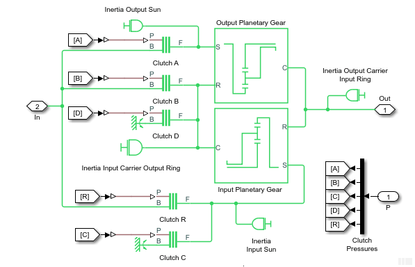
The transmission subsystem contains four clutches, two planetary gears, and four inertias (rotating bodies). Ignoring the reverse gear and its clutch, this transmission has four possible (forward) gear settings. Exactly two clutches must be locked at any one time for the transmission to engage and to avoid conflicting constraints on the gear motions.
CR-CR 4-Speed Transmission Subsystem
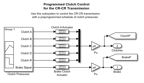
The Clutch Control variant subsystem provides the pressures that lock the necessary clutches. In its default state, the clutch controller is programmed to move the transmission through a fixed sequence of gears, then unlock all the transmission clutches. This control program allows the driven shaft to “coast” for a time, and then engage and lock the brake clutch to stop the driven shaft.
Clutch Control Subsystem
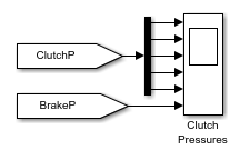
The Scopes subsystem provides Scope blocks to display the clutch pressure and the input and output shaft velocity signals.
Scopes Subsystem
Run the Model
To display the CR-CR driveline model behavior:
Open the Scopes subsystem and then the Scope block. Close the Scopes subsystem.
Click Start. The model steps through the gears and then brakes.
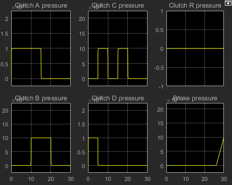
Observe how the clutch pressure signals move the transmission into one gear after another, at 0, 5, 10, and 15 seconds of simulation time. To determine which gear settings the model is implementing, compare these clutch pressure signals to the clutch schedule in the CR-CR transmission subsystem. The model steps through gears 1, 2, 3, and 4, before coasting and then braking.
To compare the angular velocities of the input and output shafts, click Plot speeds. A figure that contains the Shaft Speeds and Clutch States opens.

In the transmission, the two planetary gears are coupled in different ways in the different gear settings, producing different relationships between the driven and driver shaft velocities. The effective drive ratio of output to input shafts is the reciprocal of the ratio of output to input angular velocities.
Zoom to observe the results for the shaft speeds 20–26 seconds.
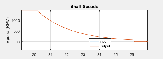
The transmission clutch pressures drop to zero, and the transmission disengages. The transmission ceases to transfer angular motion and torque from the driver to the driven shaft, and the driven shaft continues to spin from inertia alone. A small kinetic friction damping gradually slows the driven shaft over the next six seconds.
At 26 seconds of simulation time, the brake clutch pressure begins to rise from zero, and the brake clutch engages. The driven shaft decelerates more drastically now. 26.0–26.2 seconds, the brake clutch locks, and the driven shaft stops rotating completely.
Modify the Model
You can modify this example model to explore other Simscape Driveline features. Here you modify and rerun the model to investigate two aspects of its motion.
Measure the effective drive ratio of the CR-CR transmission in each gear setting that it steps through.
Change the gear sequence.
Measuring the Drive Ratio of the CR-CR Transmission States
A transmission is a set of coupled gears. For a particular transmission gear setting, the ratio of driven (output) shaft velocity to the driver (input) is fixed. The reciprocal ratio, the drive ratio, is like a gear ratio of an individual gear coupling, but for the whole transmission.
The drive ratio is the ratio of input to output shaft velocities. Add and connect the necessary Simulink blocks to measure the drive ratio for the CR-CR 4–speed transmission.
Collect data for the angular velocity for the driver shaft:
Make a copy of the S sensor subsystem that is connected to the Out port of the transmission subsystem. The output sensor captures the angular velocity of the driven shaft.
Connect the new sensor subsystem to the connector between the input shaft assembly and the In port of the transmission subsystem.
To calculate the drive ratio, from the Simulink Library Browser, from the Simulink > Math Operations library, add a Divide block.
To visualize the drive ratio, add and configure a Scope block:
Make a copy of the Shaft Speed scope block.
Change the name the new scope block to
Drive Ratio.Open the Drive Ratio block.
Open the configuration parameters for the scope.
On the Display tab, set the Y-limits (Minimum) to
0and the Y-limits (Maximum) to6.Connect the block as shown in the figure.
Label the input signal to the Drive Shaft block as
Drive Ratio.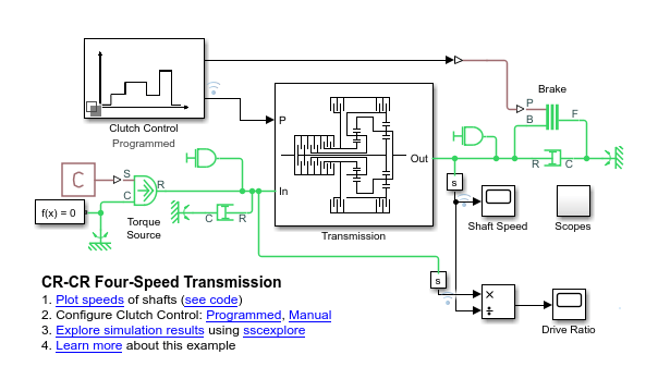
Simulate the model. Observe how the drive ratio steps through a sequence of five-second states, in parallel with the clutch pressures and clutch modes, until it reaches 20 seconds. The drive ratio measurement after 20 seconds is not meaningful because the transmission is uncoupled.
Just after 26 seconds, the driven shaft velocity drops to zero, and the Divide block produces divide-by-zero warnings at the MATLAB command line.
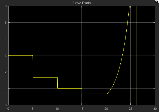
Consult the table, Clutch Schedule for the CR-CR 4-Speed Transmission. Check the drive ratios for each gear, 1, 2, 3, and 4, in terms of the gear ratios of the two Planetary Gears in the transmission. Determine the numerical values for these drive ratios for gear settings 1, 2, 3, and 4. Then check them against the values displayed in the Drive Ratio scope.
The drive ratio sequence is 3, 5/3, 1, and 2/3, respectively, for the first, second, third, and fourth intervals of five seconds each.
Changing the Transmission Gear Sequence
When you first open the CRCRFourSpeedTransmission example,
the Clutch Control variant subsystem is programmed to step through CR-CR gear
settings 1, 2, 3, and 4, before disengaging. Modify it to step through settings
1, 2, 3, and 1, then disengage. The fourth gear requires that A is free, B is
locked, C is locked, and D is free. Modify the clutch pressure signal sequence
from 15 to 20 seconds so that the transmission is set in first, not fourth,
gear. The first gear requires clutches that A and D are locked and clutches B
and C are free.
Determine the clutch states that correspond to first gear. Refer to table Clutch Schedule for the CR-CR 4-Speed Transmission.
Double-click the Clutch Control subsystem.
In the Clutch Control subsystem, double-click Programmed.
In the Programmed subsystem, double-click Clutch Pressures. The signal builder window opens with the clutch pressure signals.
In the time interval 15–20 seconds, update clutch signals A through D to match first gear. Clutches A and D must lock, while clutches B and C must remain free. Specify a signal value of one to lock a clutch, zero to unlock it.
Modified CR-CR 4-Speed Transmission Clutch Pressures

Run simulation.
Clutch pressures, clutch modes, and driven shaft velocities in the time interval 15–20 seconds now correspond to first gear. Refer to the Drive Ratio plot for the updated model. The ratio has changed from 2/3 (fourth gear) to 3 (first gear) accordingly.
