Design IBIS-AMI Models to Support Rx Decision Time
This example shows how to create Rx AMI models that support Rx Decision Time as defined in the IBIS (I/O Buffer Information Specification) version 7.1, by modifying the library blocks in SerDes Toolbox™. This example will use a typical SerDes Rx AMI model to demonstrate the setup.
Background
In the AMI Init flow the IBIS-AMI model delivers to the EDA tool an impulse response, but no information about any clock that might be recovered from the signal. To apply statistical analysis to this information, the EDA tool must determine the time at which it expects the signal to be sampled at the data decision point. The method used to determine this time is not defined in the specification so depending on the algorithm used, each EDA tool may come up with a slightly different clock location, which in turn can result in inconsistent statistical results across EDA tools.
For more consistent results, the EDA tool should use a time determined by the receiver IBIS-AMI model instead of an internal algorithm. IBIS 7.1 introduced a new AMI reserved parameter, Rx_Decision_Time, which is passed from the Rx AMI model to the EDA tool to specify the exact time to sample the impulse response.
This example introduces Rx Decision Time in SerDes Toolbox by showing how to generate and test an IBIS-AMI executable that supports Rx_Decision_Time.
Rx IBIS-AMI Model Setup in Simulink
To begin, load the Rx Decision Time Simulink model and review the model setup. Start by typing the following command:
>> open_system('rx_decision_time.slx')
This will bring up the following SerDes system:

Review Simulink Model Setup
This Simulink SerDes system contains the standard configuration: Stimulus, Tx, Analog Channel and Rx blocks. The setup of each of these blocks is in their default configuration and will be reviewed below.
Configuration Block
Symbol Time is set to
100.0ps (10.0Gbps).Target BER is set to
1e-06.Signaling is set to
Differential.Samples per Symbol and Modulation are kept at default values, which are
16andNRZ(nonreturn to zero), respectively.
Stimulus Block
The Stimulus block is set to default values.
Tx Block
The Tx contains no equalization blocks. Since this example is focused on the Rx model, the Tx block is untouched.
Analog Channel Block
Channel loss is set to
8dB.Impedance is set to
100ohms.Target Frequency is set to
5.0GHz, which is the Nyquist frequency for 10.0 GHzThe Tx Analog model is set up so that Voltage is
1.0V, Rise time is10ps, R (output resistance) is50 ohms, and C (capacitance) is0.1pF.The Rx Analog model is set up so that R (input resistance) is
50ohms and C (capacitance) is0.2pF.
Rx Block
The Rx block contains 3 equalization blocks: a CTLE block with 9 DC Gain and Peaking Gain settings, a DFE block that uses four DFE taps with Initial tap weights set to 0, and a SatAmp block with Limit set to 1.2V and the Linear gain set to 1V/V
Enable Rx Decision Time
To enable Rx Decision Time, open the SerDes IBIS-AMI Manager, switch to the AMI – Rx Tab, and click on Reserved Parameters. Under General, check the box for Rx_Decision_Time, then click OK. This will add the Rx_Decision_Time parameter to the Reserved Parameters sections of the Rx AMI model.
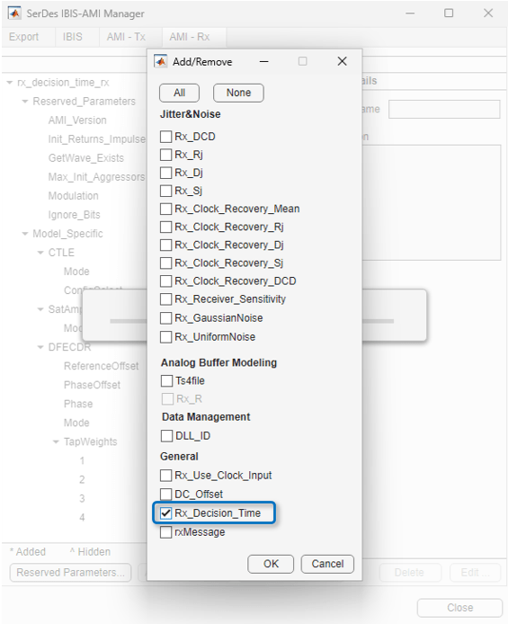
Note that the default Type for Rx_Decision_Time is UI, but this can be changed to Float by clicking on the Edit button. Keep this Type in mind if you decide to customize the calculation of Rx_Decision_Time.
After pressing OK, the dialog closes and you will get the following pop-up:

If you wish to run Refresh Init later, clicking on OK will do nothing and close the dialog.
Clicking on Refresh Init will add the Rx_Decision_Time parameter to the Init code. This parameter is automatically associated with the parameter DFECDRPhase, which is the clock phase output of the DFECDR block.

If your goal for Rx_Decision_Time was only to achieve clock location consistency across EDA tools, you are now done with the implementation. The next steps are to Run the Simulink Model and then Generate IBIS-AMI Models.
If you would like to customize the calculation of Rx_Decision_Time, see Customizing the Value of Rx Decision Time.
Run the Simulink Model
The Simulink model is ready to run. Press the run button to launch the simulation.
As the simulation runs, the Time Domain eye diagram gets constantly updated. The eye diagram should look like the following:

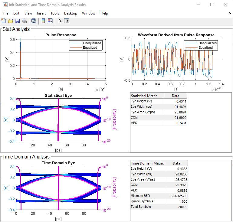
After the simulation is complete, the Init Statistical and Time Domain Analysis Results plot becomes available. The clock PDF shown in the Statistical Eye has now been placed using the value of Rx_Decision_Time:
Customizing the Value of Rx Decision Time
If you would like to use a value for Rx_Decision_Time other than the Phase output of the CDR or DFECDR, this is accomplished by customizing the “Custom user code area” in the Initialize MATLAB® function block.
If you have not already done so, you must first run Refresh Init from the Init block mask by pressing the Refresh Init button:
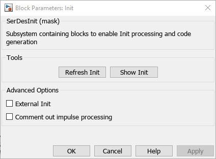
You can then view the Init code by clicking on the Show Init button.
If you review the Init code, you will see that the Rx_Decision_Time parameter has been automatically associated with the parameter DFECDRPhase, which is the clock phase output of the DFECDR block as noted previously. However, you will also see that this association was made after the Custom user code area, which means that any code entered in the Custom user code area above will be completely ignored as Rx_Decision_Time gets redefined in the Impulse response processing section. You should also note that since the association was made outside of the Custom user code area, if you were to manually remove this association it will be added back in the next time Refresh Init is run.

Comment out impulse processing
These limitations are resolved by using the option to comment out the impulse response section of the Init code. Check the box for Comment out impulse processing, then run Refresh Init. Looking at the bottom of the Init code, you will see that the entire Impulse response processing via system objects section of the Init code has been commented out:

By moving the rows for Init processing (lines 74, 78 and 79 above) to the Custom user code area the impulse response process will still occur but can now be customized without being overwritten the next time Refresh Init is run.

The value of Rx_Decision_Time can now be customized without having to worry about Refresh Init overwriting the value. Keep in mind that if additional SerDes blocks are added to the Rx data path, they will also need to be manually copied to the Custom user code area.
To revert to the original configuration, simply uncheck the box for Comment out impulse processing, then Refresh Init again.
Comment out impulse processing can also be used in conjunction with External Init if desired.
Optional: External Init
By checking the box for External Init, after running Refresh Init the contents of each of the Init MATLAB function blocks are copied to txInit.m and rxInit.m files, and links to these functions are made back to the Simulink® model. It also creates a runExternalInit.m MATLAB script to run these external Init files in MATLAB.
External initialization functions allow you to only run the Init portion of the algorithmic models, directly from the MATLAB command line, without having to wait for Simulink to compile the complete model. This allows you to quickly debug or iterate on a difficult implementation. Once debugging is complete, you can leave the Tx and Rx Init functions external, or move them back inside the Simulink model by unchecking the box for External Init and running Refresh Init.
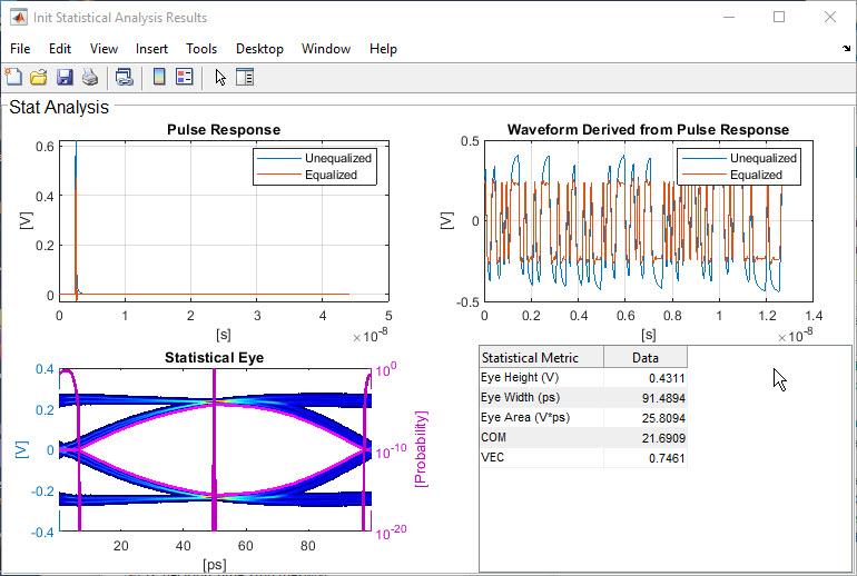
You run the external Init functions by running the MATLAB script runExternalInit which was automatically generated along with txInit.m and rxInit.m. When runExternalInit is complete, it will pop up the Init Statistical Analysis Results window. The results should be identical to those from the Init Statistical and Time Domain Analysis Results plot above:
Example Customization of Rx_Decision_Time
As an example of how to customize the calculation of Rx_Decision_Time, we will use the option to comment out impulse response processing. After selecting Comment out Impulse Processing, running Refresh Init, then copying the 3 lines to the Custom user code section, you are ready to start. For this simple example we will still use the Phase output of the DFECDR block, but we will add a new AMI parameter that allows us to adjust the resulting clock location.
Start by using the SerDes IBIS-AMI Manager to add a new parameter to the DFECDR block as follows:
1) In the AMI-Rx tab, highlight the DFECDR and click on Add Parameter…
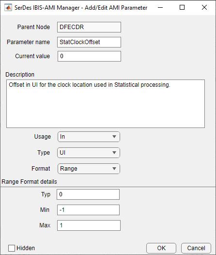
2) In the Add/Edit AMI Parameter dialog, enter the following:
Parameter name: StatClockOffset
Current value: 0
Description: Offset in UI for the clock location used in Statistical processing.
Usage: In
Type: UI
Format: Range
Typ: 0
Min: -1.0
Max: 1.0
3) Click OK to save the new parameter.
4) By default, SerDes toolbox automatically adds new parameters to the corresponding data path block.
Since the datapath blocks represent the Time Domain functionality of the AMI model, and Rx_Decision_Time is a Statistical only feature, you can delete the
StatClockOffsetconstant block from the DFECDR block.Delete the
StatClockOffsetconstant block now.
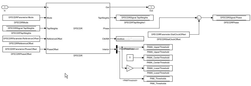
Advanced implementation: To get similar results in both Statistical and Time Domain you could use the StatClockOffset constant block to modify the value of Phase generated by the DFECDR.
In this case, do not delete the
StatClockOffsetconstant block.Use a
Sumblock to connect thePhaseoutput and theStatClockOffsetoutput.
5) Run Refresh Init on the Rx block to add the new StatClockOffset parameter to the Initialize Function.
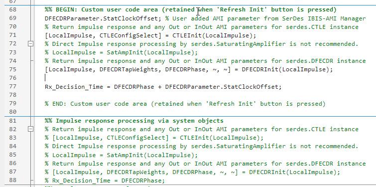
You should see the following line added to top of the custom user code section:
DFECDRParameter.StatClockOffset; % User added AMI parameter from SerDes IBIS-AMI Manager
6) Modify the Rx_Decision_Time calculation to include the value of StatClockOffset:
Rx_Decision_Time = DFECDRPhase + DFECDRParameter.StatClockOffset;
7) When completed, the Custom user code section should look something like this. Note that the impulse response processing at the bottom of the function is still commented out:
8) Test the model by running with different values for StatClockOffset.
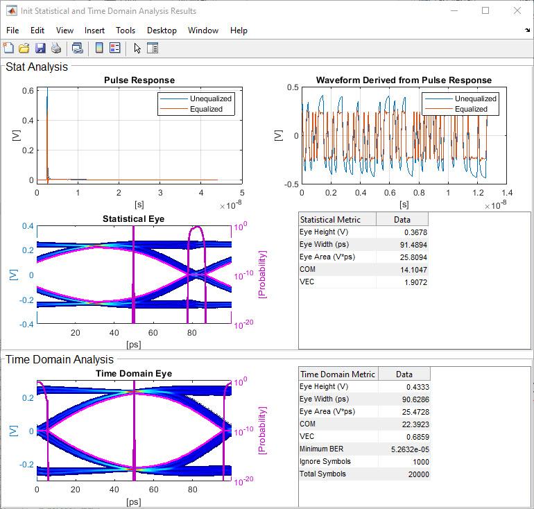
Init Statistical and Time Domain Analysis Results plot with StatClockOffset = 0.2UI:
Init Statistical and Time Domain Analysis Results plot with StatClockOffset = -0.2UI:
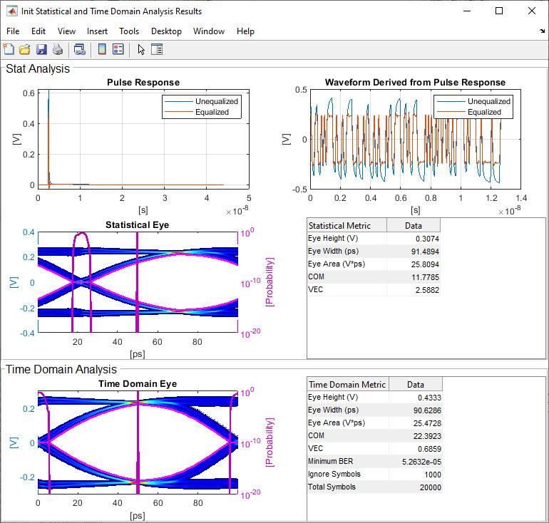
Note that unless you decided to do the advanced implementation above, the Time Domain results should not change.
Generate IBIS-AMI Models
The final part of this example takes the customized Simulink model and generates IBIS-AMI compliant model executables, IBIS and AMI files for the Rx Decision Time enabled receiver.
Open the Block Parameter dialog box for the Configuration block and click on the Open SerDes IBIS-AMI Manager button.
Export Models
On the AMI-Rx tab, verify that the value for StatClockOffset is set to 0.
On the Export tab in the SerDes IBIS/AMI manager dialog box.
Update the Rx model name to
rx_decision_time_rx.Note that the Tx and Rx corner percentage is set to
10. This will scale the min/max analog model corner values by +/-10%.Verify that Dual model is selected for the Rx AMI Model Settings. This will create a model executable that support both statistical (Init) and time domain (GetWave) analysis.
Set the Rx model Bits to ignore value to
1000to allow enough time for the external clock waveform to settle during time domain simulations.Verify that Models to export is set to Both Tx and Rx.
Set the IBIS file name to be
rx_decision_time.ibsPress the Export button to generate models in the Target directory.
Test Generated IBIS-AMI Models
The Rx Decision Time receiver IBIS-AMI model is now complete and ready to be tested in any industry standard AMI model simulator that supports the Rx_Decision_Time parameter per the IBIS 7.1 specification.
You can use Signal Integrity Link to automatically generate a Signal Integrity Toolbox Parallel Link Designer or Serial Link Designer project with the newly created AMI models already instantiated. This is an excellent way to test the new AMI model executables and verify that all features are working correctly.