Solution Space
You can setup solution spaces to create parameter sweeps in the Serial Link Designer and Parallel Link Designer apps. Some variables are populated in the solution space by default, while others come from the schematic elements and their settings. The values are typed into fields, lists, or range/steps depending on the variable type. There are two modes in a solutions space panel: Permutation mode (default) and Case mode.
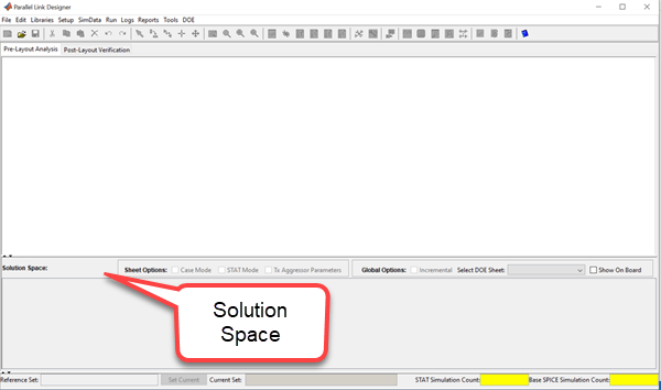
Permutation Mode
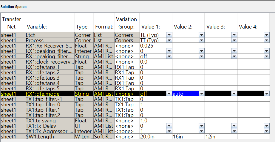
In this mode, each row in the solution space is treated as an independent variable,
unless the variable is in the same variation group. The number of simulations represented in
the solution space contains all the combinations of all the variable values. The initial
simulation count for a schematic sheet is 1. But as you sweep the variables in solution
space, the simulation count increases. The increase depends on the number settings assigned
to the added variable, multiplied by the simulation count. For example, sweeping the
transmission line length over three values and varying DFE mode between
off and auto results in six simulations to
run.
Defining Global Variables
You can define global variables in the solution space panel that let you easily reuse the same values for several variables. Global variables are visible to all sheets in an interface.
To create a new global variable:
Right click on a row of the solution space table and choose. Add New Global Variable to launch the dialog box.
Enter a name and select the variable type from the list.
Click OK to create the variable and close the dialog or Apply to create the variable and leave the dialog box open.
Add values for the global variable in the Value columns of the solution space table.
To use a global variable put the variable name as the value for any non-global variable of the same type.
Sweeping Parameter Values
You can set up parameter sweeps for schematic elements from the Element Properties dialog box for each element type. You can launch the dialog box from Setup > Element Properties or by double clicking on elements.
Creating Range of Values
To specify a start, stop and number of cases instead of entering individual values, right click on a row and select Set to Range from the menu.
Variation Groups
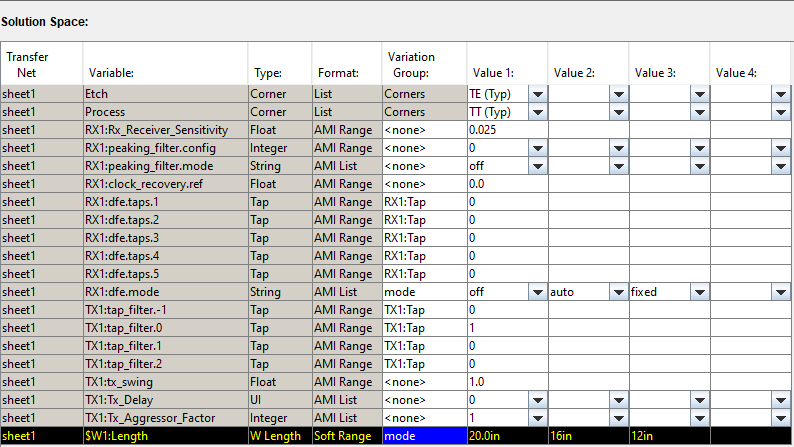
In the Solution Space panel, the Variation Group column lets you control the
combinations of variable values that the app simulates. You can set up the variation
groups to meet a wide variety of simulation needs. By associating two or more rows with
the same variation group name, you can lock those variations to sweep together. This
reduces the number of simulations to run. For example, consider a schematic sheet where
the length is varied between 20 inches, 16 inches, and 12 inches. The DFE mode is varied
between off , fixed, and auto.
The simulation count would be 9 without a variation group between the length and DFE mode.
By varying the two groups together as variation group mode, you can
reduce the simulation count from 9 to 3.
Designator Timing Maps
For some designs it is useful to specify the mapping of designators to clock designators explicitly. An example is DDR3, where the clock is fly-by but other nets have point-to-point topologies. The explicit mapping is done through a parameter on the schematic. One parameter is used for each designator.
To place a parameter on the schematic use the parameter symbol. The name of the parameter is:
$designatortimingmap%<designator_name>
where designatortimingmap identifies the parameter as a designator
timing map parameter and <designator_name> is the name of a
designator on the schematic that the map will apply to. The $ creates a
solution space table entry. The values in the solution space table are of the form:
<clock_sheet_name>:<clock_designator_name>
where <clock_sheet_name> is the name of the clock schematic
sheet that has the clock designator and <clock_designator_name> is
the name of the clock designator.
For example, if a design has a DQS that is point-to-point, so all DQS nets can be represented by a single Transfer Net, and a CK that is fly-by with five designators, the single memory designator on the dqs schematic must be mapped to five ck Transfer net designators, one for each DQS on the actual board. If the memory designator on the dqs schematic is named sdram, the parameter would be named:
$designatortimingmap%sdram
If the designators on the ck schematic are named sdram1-sdram5, the solution space table values for this parameter would be:
ck:sdram1, ck:sdram2, ck:sdram3, ck:sdram4, ck:sdram5
The dqs timing analysis results will be reported for each of the five designators. Without the mapping parameter the dqs results will be rolled up into one margin that is the worst case of all five designators.
Sweeping Package Pins or Models
The following parameters allow an automatic sweep of the package models for a given TNET designator. This sweep only involves those signals included in a specific designator. This is a pre-layout only function.
To evoke this function:
Add two .PARAM functions onto the schematic sheet and fill in the following Parameter Element Properties:
Key = pkg_sweep_designator, Value =
              $pkg_sweep_designator:Param
Key = pkg_sweep_pin, Value = $pkg_sweep_pin:Param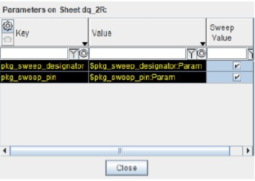
The solution space contains the designator and package pins available for sweep.

Sweeping S-Parameters
In order to sweep s-parameters, import the parameters after merging the wrappers into the same file. Consider an imported s-parameter file with four wrappers merged.
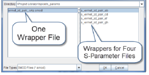
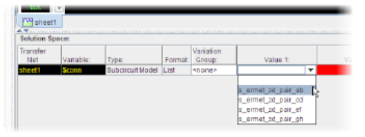
On the left of the sweep window is the one wrapper file. When you select that file the right side shows the wrappers in that file. The name of the wrapper is the same as the Touchstone file containing the S-Parameter data. To set the symbol for a particular file, select one of the wrappers on the right side of the window and click OK. To sweep, double-click on the symbol to launch the element properties dialog for s-parameters and select Sweep Model. This creates a variable in the solution space with the value columns containing a list of the models in the wrapper file.
Case Mode

In case mode each column is a separate simulation case. This makes it easier to import or export the solution space table. The column header for each case contains the case name. You can perform several operations by choosing the appropriate column headers:
| Generate Cases | Generate Cases creates cases from the permutation mode solution space. Each simulation from the permutation mode solution space will become one case. |
| Set to Default Case | Removes all cases except the first case. |
| Rename Case | Renames the case. |
| Insert New Case | Inserts a column for a new case to the right of the selected column. |
| Remove Selected Case | Removes the selected column. |
| Write Solution Space | The solution space table in Case Mode can be written out as a csv (comma separated value) file using the Setup | Write Solution Space menu item. The file has one line per case and one column per variable. |
| Read Solutions Space | The solution space table in Case Mode can be populated by reading a csv (comma separated value) file using the Setup | Read Solution Space menu item. The file has one line per case and one column per variable. The variable names must match the variable names already in the table, and the values in the csv files must be legal values. |
Note
The values of the AMI parameters with value type specified as Format are set by the model maker. They are not intended to be changed by the model user. Even if you change the values by editing the AMI file, it may result in the new value being ignored, a model error, or a model crash. Thus, all AMI parameters that have Format Value type are not displayed in the solution space.
See Also
Serial Link Designer | Parallel Link Designer