Mixer
Model RF and IQ modulator and RF and IQ demodulator with impairments and noise
Libraries:
RF Blockset /
Idealized Baseband
Description
The Mixer block models four complex baseband mixers and with impairments and noise. The four mixer types that the block models are Modulator, Demodulator, IQ Modulator, and IQ Demodulator. Impairments include IQ gain and phase mismatch where appropriate, while noise includes both system and LO phase noise.
Note
Idealized Baseband library blocks assume input and output ports are matched. For more information on port signal power, see Power Ports and Signal Power Measurement in RF Blockset.
Idealized Baseband library blocks are single carrier with assumed carrier frequency value. Therefore the Ideal Baseband Mixer block can produce only a single sideband output.
Mixer block mask icons are dynamic and indicate the current set of applied noise parameters. For more information, see Mixer Block Icons.
Examples
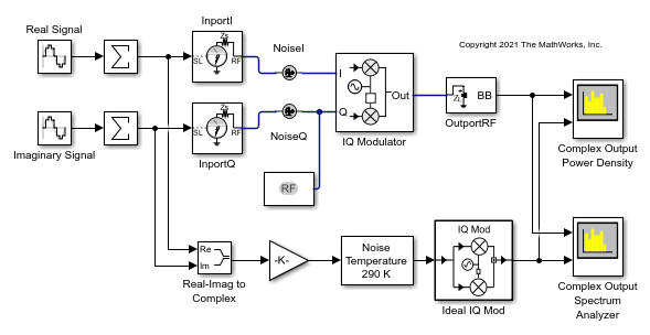
Modulate Quadrature Baseband Signals Using IQ Modulators
Modulate quadrature baseband signals using two different RF Blockset™ blocks. You can use either an idealized baseband Mixer block or a circuit envelope IQ Modulator block in your model to modulate quadrature baseband signals to the RF level. Observe the impairments in the modulated output signal due to gain imbalance, third-order intercepts (OIP3) and system noise in the complex output power density and output power spectrum analyzers.
Ports
Input
Time-dependent input signal, specified as a real scalar, real column, complex scalar, or complex column. A column represents consecutive time points.
Data Types: double | single
Output
Time-dependent output signal , returned as a complex scalar or complex column. The size of the output time dependent signal is equal in size to the input time dependent signal.
Data Types: double | single
Parameters
Main Tab
Mixers available in the Mixer block, specified as one of the following:
mod— Modulatordemod— Demodulatoriqmod— IQ Modulatoriqdemod— IQ Demodulator
For more information, see Mixer Architectures and Design Equations.
Sidebands of the mixer, specified as one of the one of the following:
lowerupper
For more information, see Mixer Sidebands.
Dependencies
To enable this parameter, set Mixer
type to mod.
Since R2024b
RF carrier frequency for the mixer model, specified as a real number in Hz.
Dependencies
To enable this parameter, set Mixer
type to mod,
demod, iqdemod.
Since R2024b
Local oscillator frequency for the mixer model, specified as a real number in Hz.
Dependencies
To enable this parameter, set Mixer
type to mod,
demod, iqmod.
Conversion gain for the mixer model, specified as a real number in dB.
Type of simulation to run, specified as one of the following:
Code generation— Simulate model using generated C code. The first time you run a simulation, Simulink® generates C code for the block. The C code is reused for subsequent simulations, as long as the model does not change. This option requires additional startup time, but the speed of the subsequent simulations is faster thanInterpreted execution.Interpreted execution— Simulate model using the MATLAB® interpreter. This option shortens startup time speed, but the speed of the subsequent simulations is slower thanCode generation. In this mode, you can debug the source code of the block.
Impairments Tab
LO phase offset, specified as a real number in degrees.
Dependencies
To enable this parameter, set Mixer
type to mod or
demod.
IQ gain imbalance, specified as a nonnegative real numbers in decibels.
Dependencies
To enable this parameter, set Mixer
type to iqmod or
iqdemod.
IQ phase imbalance, specified as a real number in degrees.
Dependencies
To enable this parameter, set Mixer
type to iqmod or
iqdemod.
Type of third-order nonlinearity type in the cubic polynomial model, specified as
IIP3, OIP3, IP1dB,
OP1dB, IPsat, or
OPsat.
For more information, see Nonlinearities in Idealized Baseband Mixer Block.
Input third-order intercept point, specified as a real positive number in dBm.
Dependencies
To enable this parameter, set Type of
Non-Linearity to IIP3.
Output third-order intercept point, specified as a real positive number in dBm.
Dependencies
To enable this parameter, set Type of
Non-Linearity to OIP3.
Input 1 dB compression point, specified as a real positive number in dBm.
Dependencies
To enable this parameter, set Type of
Non-Linearity to IP1dB.
Output 1 dB compression point, specified as a real positive number in dBm.
Dependencies
To enable this parameter, set Type of
Non-Linearity to OP1dB.
Input saturation point, specified as a real positive number in dBm.
Dependencies
To enable this parameter, set Type of
Non-Linearity to IPsat.
Output saturation point, specified as a positive real number in dBm.
Dependencies
To enable this parameter, set Type of
Non-Linearity to OPsat.
This button plots the power characteristics based on the value you specify in the Gain (dB) parameter in the Main tab and the Non-Linearity in the Impairments tab. When plotting power characteristics, the block ignores all other impairment values.
For more information, see Plot Power Characteristics.
Noise Tab
Select this parameter to add mixer noise to the input signal. Once you select this parameter, the parameters associated with Include mixer noise are displayed and the mixer components in the block icon are shaded gray.
For more information, see Mixer (System) Noise Simulations.
Type of noise, specified as one of the following:
noise-temperature— Noise temperatureNF— Noise figurenoise-factor— Noise factor
For more information, see Mixer (System) Noise Simulations.
Dependencies
To enable this parameter, select Include mixer noise.
Noise temperature to model the mixer noise, specified as a nonnegative real number in kelvin.
Dependencies
To enable this parameter, select Include mixer
noise and set Mixer noise
type to noise-temperature.
Noise figure to model the mixer noise, specified as a nonnegative real number in decibels.
Dependencies
To enable this parameter, select Include mixer
noise and set Mixer noise
type to NF.
Noise factor to model mixer noise, specified as a positive integer scalar greater
than or equal to 1
Dependencies
To enable this parameter, select Include mixer
noise and set Mixer noise
type to noise-factor.
Source of initial seed used to prepare the Gaussian random number noise generator, specified as one of the following:
auto— When you set Seed source, mixer noise toauto, seeds for each mixer instance are generated using a random number generator. The reset method of the instance has no effect.user— When you set Seed source, mixer noise toauto, the value provided in the Seed for mixer noise is used to initialize the random number generator and the reset method resets the random number generator using the Seed for mixer noise property value.
Dependencies
To enable this parameter, select Include mixer noise.
Seed for the random number generator, specified as a nonnegative integer less than 232. Use this value to initialize the random number generator.
Dependencies
To enable this parameter, select Include mixer
noise and set the Seed source, mixer
noise parameter to user.
Select this parameter to add frequency-depended LO phase noise to the LO signal. Once you select this parameter, the parameters associated with the Include phase noise are displayed and the LO source inside the block icon is shaded gray.
For more information, see Phase Noise in Mixer Block.
Phase noise level relative to carrier, specified as negative real scalar or vector in dBc/Hz.
Note
The number of terms listed in the Phase noise level (dBc/Hz) parameter must equal the number of terms in the Frequency offset (Hz) field.
Dependencies
To enable this parameter, select the Include phase noise parameter.
Data Types: double
Specify the frequency offset as a positive real scalar or vector of positive increasing real values of type double in Hz.
Note
The number of terms listed in the Frequency offset (Hz) must equal the number of terms in the Phase noise level (dBc/Hz) field.
Dependencies
To enable this parameter, select the Include phase noise parameter.
Select this parameter to automatically determine number of frequency bins used in
a two-sided phase noise spectrum. You can also set the number of frequency bins using
the Number of signal samples and Sample rate
(Hz) parameters when you set the Automatic frequency
resolution parameter is set to off.
Dependencies
To enable this parameter, click Include phase noise.
Number of samples in the time-domain signal for the blocks sample time or the
number of frequency lines (bins) in the signals two-sided frequency spectrum to
achieve the required frequency resolution for a specified Frequency offset, specified
as a real nonnegative integer less than or equaled to 65536.
Frequency resolution increases as the value of number of signal samples increases.
Note
The value of this parameter must be set to a power of two.
Dependencies
To enable this parameter, select the Include phase noise parameter and deselect Automatic frequency resolution.
Source of initial seed used to prepare the Gaussian random number LO phase noise generator, specified as one of the following:
auto— When you set the Seed source, phase noise toauto, seeds for each mixer instance are generated using a random number generator. The reset method of the instance has no effect.user— When you set the Seed source, phase noise touser, the value provided in the Seed for phase noise is used to initialize the random number generator and the reset method resets the random number generator using the Seed for phase noise property value.
Dependencies
To enable this parameter, select the Include phase noise parameter.
Seed for the random number generator, specified as a nonnegative integer less than 232. Use this value to initialize the random number generator.
Dependencies
To enable this parameter, select Include phase
noise and set the Seed source, phase
noise parameter to user.
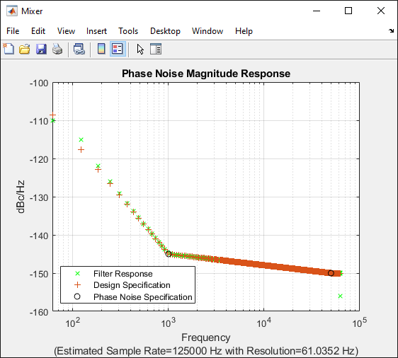
This button plots the phase characteristics based on the parameters specified on the Noise tab and either the block sample time when a simulation has been performed or estimated from the Frequency offset (Hz) parameter values.
For more information, see Plot Phase Noise Characteristics.
Algorithms
Architectural models for the Mixer block are shown here. Mixer and phase noise for all cases are included here.
Modulator and demodulator architectures includes system noise, phase noise, and nonlinear polynomials to translates the carrier. A random number generator is used as an input to generate phase noise.

The output of the ideal modulator and demodulator circuit with nonlinearities, Yout, is given by this equation.
Where,
The nonlinear polynomial coefficients, c1 and c3 , are provided in Nonlinearities in Idealized Baseband Mixer Block.
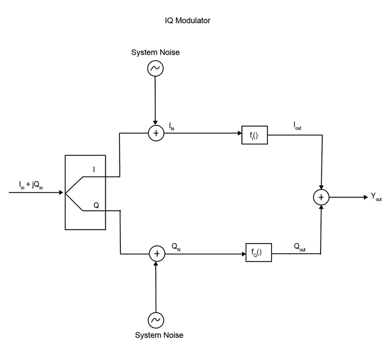
The IQ modulator primary consists of two mixers, fI() and fQ(). The Mixers convert baseband signals to RF signals and are commonly used in direct conversion architectures. The fI() and fQ(), are responsible for introducing gain, gain imbalance, phase imbalance, and nonlinearities into the IQ demodulator.

The output of IQ Modulator, Yout, is given as
where,
The nonlinear polynomial coefficient c3 are provided in Nonlinearities in Idealized Baseband Mixer Block. The modulators linear gains are c1 and c1Q are provided in this equation.
where,
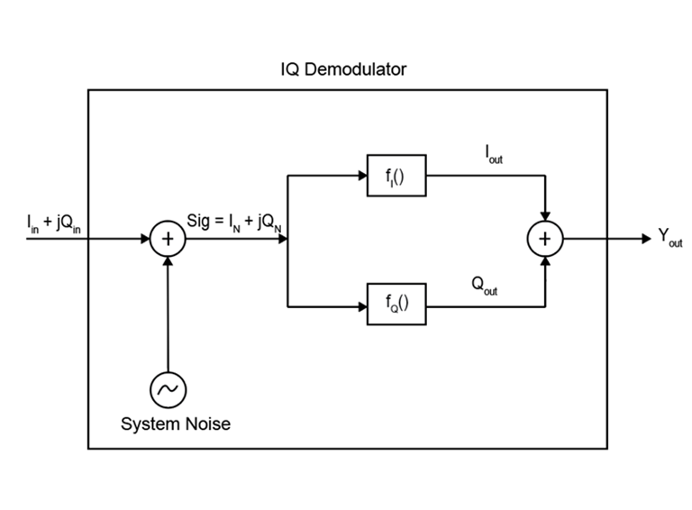
The architecture of an IQ demodulator is given below. The in-phase, Iout, and quadrature component, Qout, of the modulated signal are the output of the fI() and fQ(), respectively. The mixers, fI() and fQ() are responsible for introducing gain, gain imbalance, phase imbalance, and nonlineatites into the IQ demodulator.

The output of the IQ Demodulator, Yout, is given as
where,
The nonlinear polynomial coefficient c3 are provided in Nonlinearities in Idealized Baseband Mixer Block. The modulators linear gains c1 and c1Q are provided in this equation.
where,
The expression for Sout shows the production of upper and lower sidebands, (ωlo+ωin) and (ωlo−ωin), and the effect of the difference values of the input carrier and LO signal on the sine function. Applying the trigonometric identity
to the a mixer product expression, Sout = Sinx Slo yields
where, the term connected to the higher output frequency,
ωin+ωlo, is the
upper sideband and
|ωlo-ωin| is the
lower sideband. Since Ideal Baseband library blocks only support a single carrier signal,
the desired output sideband must be selected. Set the Mixer type
parameter to mod.
For demodulators, only the lower sideband can be used as an output.
When selecting a Mixer type, this table provides the available sideband options LO phase offset (deg), I/Q gain imbalance (dB), and I/Q phase imbalance (deg).
| Mixer Type | Impairments | Noise |
|---|---|---|
| Modulator | LO phase offset and non-linearities. | LO phase offset, mixer and system noise. |
| Demodulator | ||
| IQ modulator and demodulator | Gain imbalance, phase imbalance, and non-linearities. |
This table shows you how the icons on this block will vary based on how you set the Parameters on the block.
| Mixer Type | Include Mixer Noise | Include Phase Noise: off | Include Phase Noise: on |
|---|---|---|---|
Modulator | off |
|
|
on |
|
| |
| Demodulator | off |
|
|
on |
|
| |
| IQ Modulator | off |
|
|
on |
|
| |
| IQ Demodulator | off |
|
|
on |
|
|
Note
After you set the block parameters you must click the Apply button to see the icon change.
References
[1] Razavi, Behzad. “Basic Concepts “ in RF Microelectronics, 2nd edition, Prentice Hall, 2012.
[2] Kundert, Ken.“ Accurate and Rapid Measurement of IP2 and IP3,“ The Designer Guide Community, May 22, 2002.
[3] Kasdin, N.J. “Discrete Simulation of Colored Noise and Stochastic Processes and 1/f α Power Law Noise Generation.” Proceedings of the IEEE 83, no. 5 (May 1995): 802–27. https://doi.org/10.1109/5.381848.
Extended Capabilities
C/C++ Code Generation
Generate C and C++ code using Simulink® Coder™.
Version History
Introduced before R2006aThe following parameters in the Mixer block in the idealized baseband library have been renamed.
| Parameter Name Before R2024b | Parameter Name Since R2024b |
|---|---|
| Mixer sideband | Sideband |
| Conversion gain (dB) | Gain (dB) |
| Type of Non-linearity | Non-linearity |
The following parameter values in the Mixer block in the idealized baseband library have been changed:
| Parameter | Values Before R2024b | Values Since R2024b |
|---|---|---|
| Mixer type | Modulator | mod |
Demodulator | demod | |
IQ Demodulator | iqdemod | |
IQ Modulator | iqmod | |
| Mixer noise type | Noise figure | NF |
Noise temperature | noise-temperature | |
Noise factor | noise-factor | |
| Sideband | Upper | upper |
Lower | lower | |
| Seed source, phase noise | Auto | auto |
User specified | user | |
| Seed source, mixer noise | Auto | auto |
User specified | user |
The following default values in the Mixer block in the idealized baseband library have been changed:
| Parameter | Default Values Before R2024b | Default Values Since R2024b |
|---|---|---|
| Non-linearity | IIP3 | OIP3 |
| Mixer noise type | Noise temperature | NF |
When you open a model created before R2024b containing the Mixer block, the software replaces the parameter names and values as shown in the table.
The Input carrier frequency greater than LO frequency parameter has replaced by RF (Hz)and LO(Hz) parameters.
When you open a model created before R2024b containing the Mixer block, the software replaces theInput carrier frequency greater than LO frequency with RF (Hz)and LO(Hz) parameters.
Starting in this release, the extrapolated low-frequency phase noise below the first frequency point that specifies the 1/f^3 in the Mixer block is now 30 dB/decade instead of 3 dB/decade.
When you open a model created before R2023a containing the Mixer block and click the Plot Phase Characteristics button, the software scales the phase noise level in dBc/Hz on the y-axis in a phase noise magnitude response plot.
For example, open the Mixer block and select Include Phase Noise.
Set the Number of signal samples to 2^10 and click
the Apply button. Click the Plot Phase
Characteristics button to plot the phase noise magnitude response and observe
that the first frequency point that specifies the 1/f^3 in the Mixer block is
scaled to 30 dB/decade.

Starting in R2021a, the Mixer block supports modulator, demodulator, IQ modulator, and
IQ demodulator mixers with impairments and noise. The new Mixer block enables you to use
pre-R2021a functionality when the Mixer type
parameter is set to Modulator.
When you open a model from a previous release containing the Mixer block from the Idealized Baseband library, the pre-R2021a version of this block is automatically replaced with the R2021a version of this block with impairments and noise.
MATLAB Command
You clicked a link that corresponds to this MATLAB command:
Run the command by entering it in the MATLAB Command Window. Web browsers do not support MATLAB commands.
选择网站
选择网站以获取翻译的可用内容,以及查看当地活动和优惠。根据您的位置,我们建议您选择:。
您也可以从以下列表中选择网站:
如何获得最佳网站性能
选择中国网站(中文或英文)以获得最佳网站性能。其他 MathWorks 国家/地区网站并未针对您所在位置的访问进行优化。
美洲
- América Latina (Español)
- Canada (English)
- United States (English)
欧洲
- Belgium (English)
- Denmark (English)
- Deutschland (Deutsch)
- España (Español)
- Finland (English)
- France (Français)
- Ireland (English)
- Italia (Italiano)
- Luxembourg (English)
- Netherlands (English)
- Norway (English)
- Österreich (Deutsch)
- Portugal (English)
- Sweden (English)
- Switzerland
- United Kingdom (English)


