Design Analog Beamsteering for MIMO Transmitter
R2026bThis example shows how to analyze array beamforming performance, compute steering vectors, and integrate phase shifters into a system-level simulation to steer the beam 30 degrees from boresight.
Load Antenna Data
Load the single-element radiation pattern p from antennaData.mat generated from Integrate Antenna Array into MIMO Transmitter example. This pattern is used below to configure the phased array element for realistic beamforming analysis.
load("antennaData.mat", "p");
Define Uniform Linear Array for Beamforming
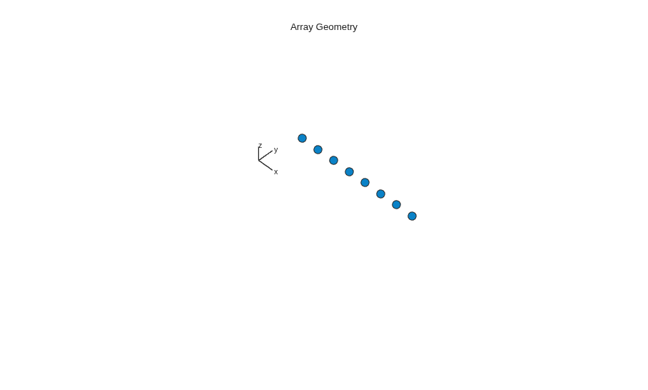
First, compute steering weights. To do this, define an 8-element uniform linear array (ULA) and set the element spacing to 6.7 mm, which corresponds to approximately half a wavelength at 27 GHz.
Array = phased.ULA(NumElements=8, ElementSpacing=0.0067, ArrayAxis="x");
Configure Custom Antenna Element Pattern
To capture the realistic element behavior, assign the measured patch antenna pattern to a custom antenna element. This ensures the beamforming analysis accounts for the actual element radiation characteristics.
Elem = phased.CustomAntennaElement;
Elem.AzimuthAngles = (-180:5:180);
Elem.ElevationAngles = (-90:5:90);
Elem.MagnitudePattern = p;
Elem.PhasePattern = zeros(37,73); % Assume uniform phase across all angles
Elem.MatchArrayNormal = false;
Array.Element = Elem;
Compute Steering Weights and Visualize Steered Pattern
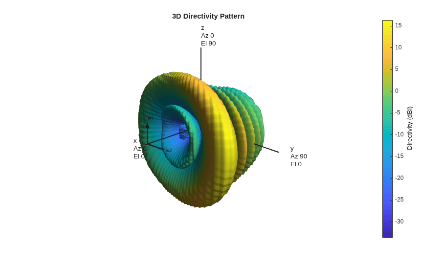
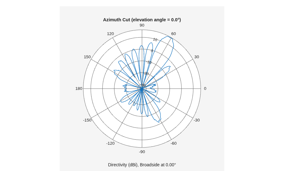
To steer the beam 30 degrees from boresight, compute the azimuth angle. For a ULA along the x-axis, boresight (broadside) is at 90 degrees azimuth, so steering 30 degrees off boresight corresponds to Az = 90-30 = 60 degrees.
Az = 90-30;

figure;
viewArray(Array, ShowNormals=false, ShowTaper=false, ShowIndex="None",...
    ShowLocalCoordinates=true, ShowAnnotation=false,...
    Orientation=[0;0;0]);

SteerVector = phased.SteeringVector(SensorArray=Array);
w = step(SteerVector, 27e9, Az);

figure;
pattern(Array, 27e9, CoordinateSystem="polar", weights=w,...
    ShowArray=false, ShowLocalCoordinates=true,...
    ShowColorbar=true, Orientation=[0;0;0],...
    Type="Directivity");

figure;
pattern(Array, 27e9, -180:180, 0, CoordinateSystem="polar", weights=w,...
    Type="Directivity");
Compute Phase Shifts from Steering Weights
The steering vector w contains complex weights with unit magnitude. Extract the phase angle of each weight to obtain the phase shift values that the analog phase shifters must apply to steer the beam.
phaseShifts = rad2deg(angle(w));
disp("Phase shifts (degrees):");
disp(phaseShifts');
Phase shifts (degrees):
  Columns 1 through 7

  -20.1530   88.4621 -162.9227  -54.3076   54.3076  162.9227  -88.4621

  Column 8

   20.1530
Integrate Phase Shifters into System-Level Simulation
To enable analog beamsteering in the full transmitter model, write the computed phaseShifts into the model workspace. Each of the eight Phase Shift blocks is parameterized as phaseShifts(1) through phaseShifts(8), reading directly from the model workspace.
The model also loads antennaData.mat via its PreLoadFcn callback, which provides patchArray to the Antenna block for full-wave EM modeling.
open_system("TXmodel_4.slx");
mws = get_param("TXmodel_4", "ModelWorkspace");
assignin(mws, "phaseShifts", phaseShifts);
assignin(mws, "Az", Az);
sim("TXmodel_4.slx")
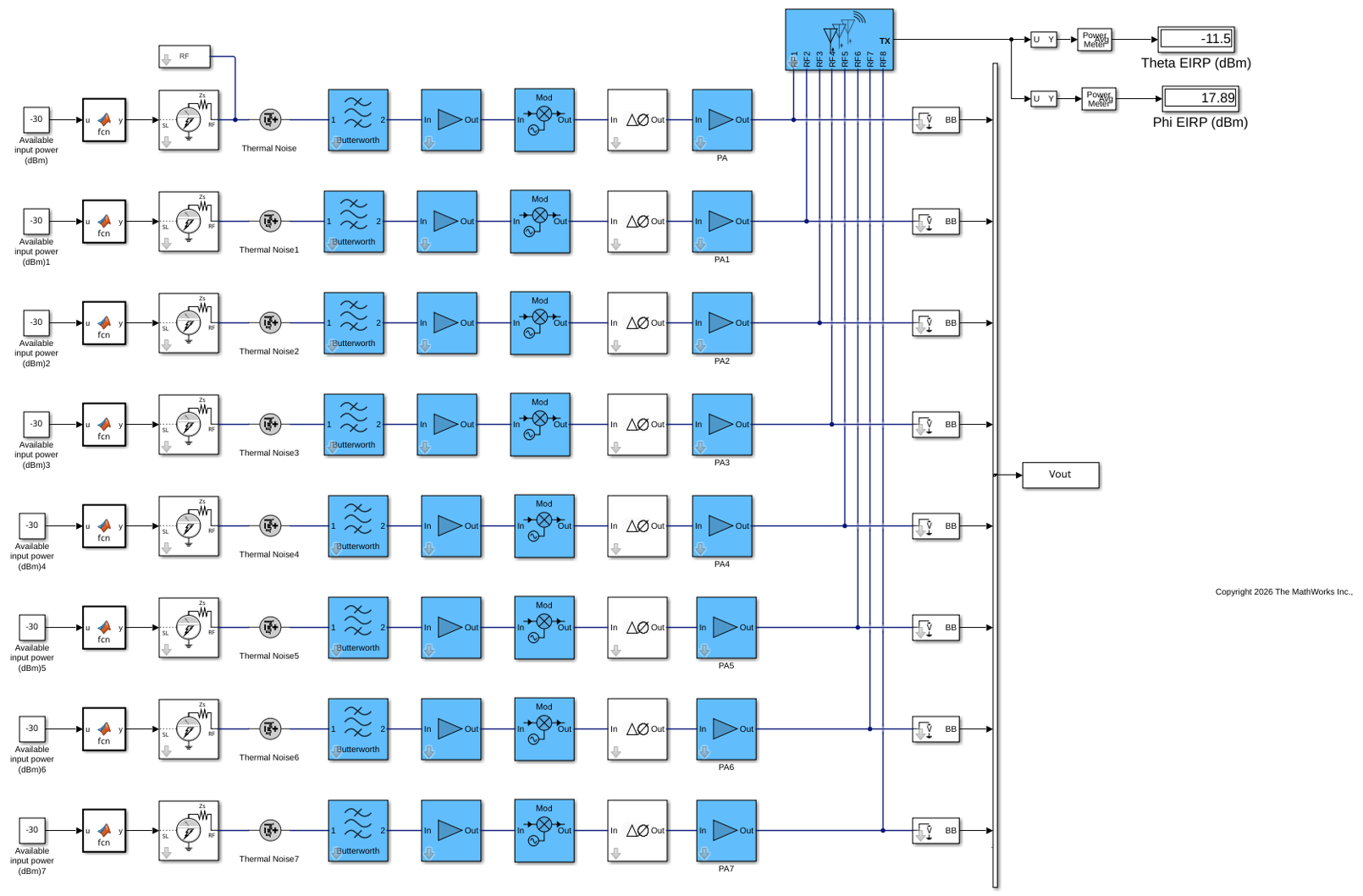
The output power is reduced because the beam is not pointing at boresight. Unlike the idealized Sensor Array Analyzer results, the system-level simulation accounts for:
Antenna mutual coupling
Impedance mismatches
RF nonlinearity
Noise
Polarization
See Also
Modeling RF mmWave Transmitter with Hybrid Beamforming | Massive MIMO Hybrid Beamforming with RF Impairments

