Design Power Divider for MIMO Transmitter
R2026bThis example shows how to design a corporate Wilkinson power divider, perform electromagnetic (EM) analysis of the printed circuit board (PCB) layout, and integrate the characterized S-parameters into a system-level simulation.
Add Ideal Power Divider to Transmitter Model
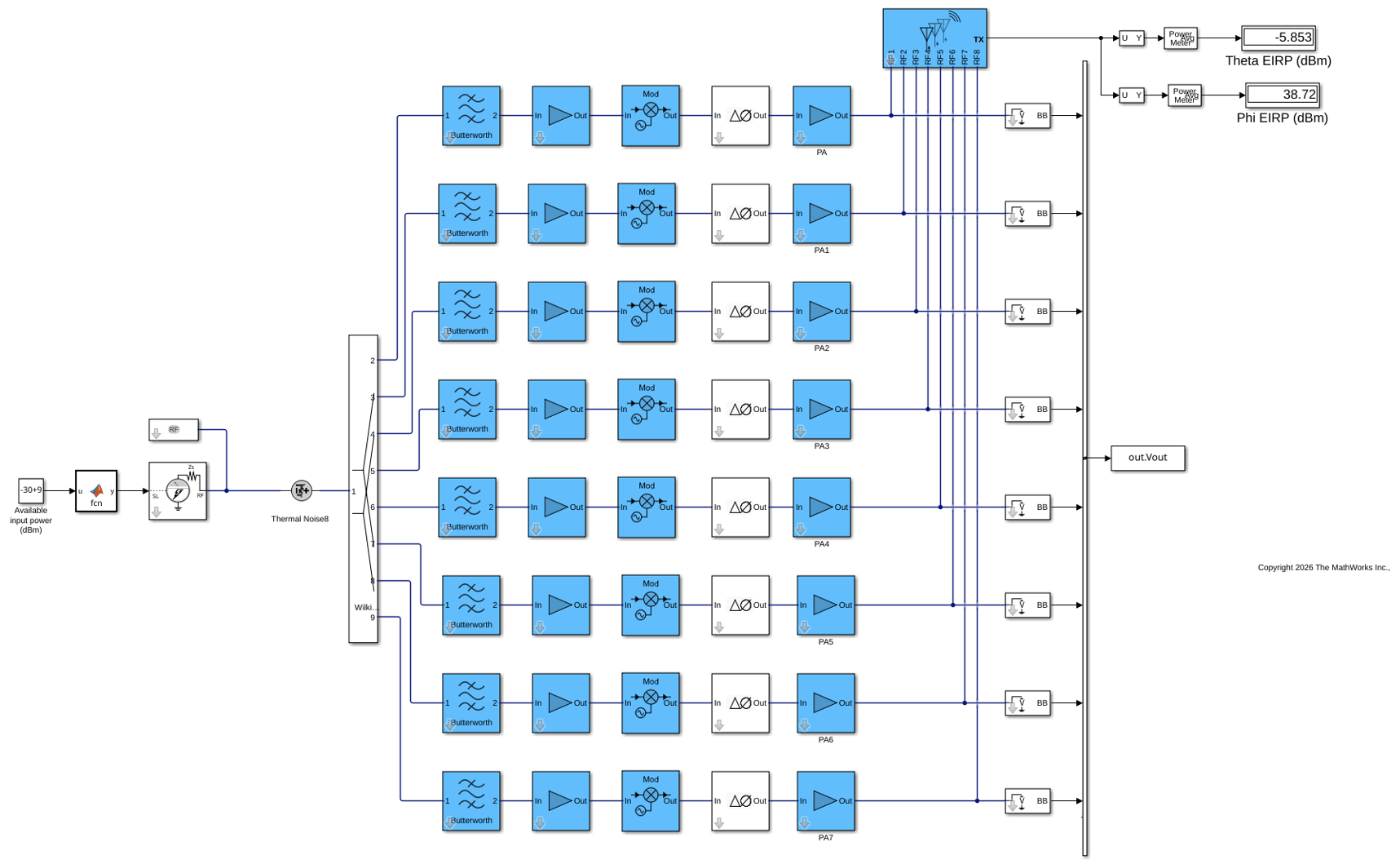
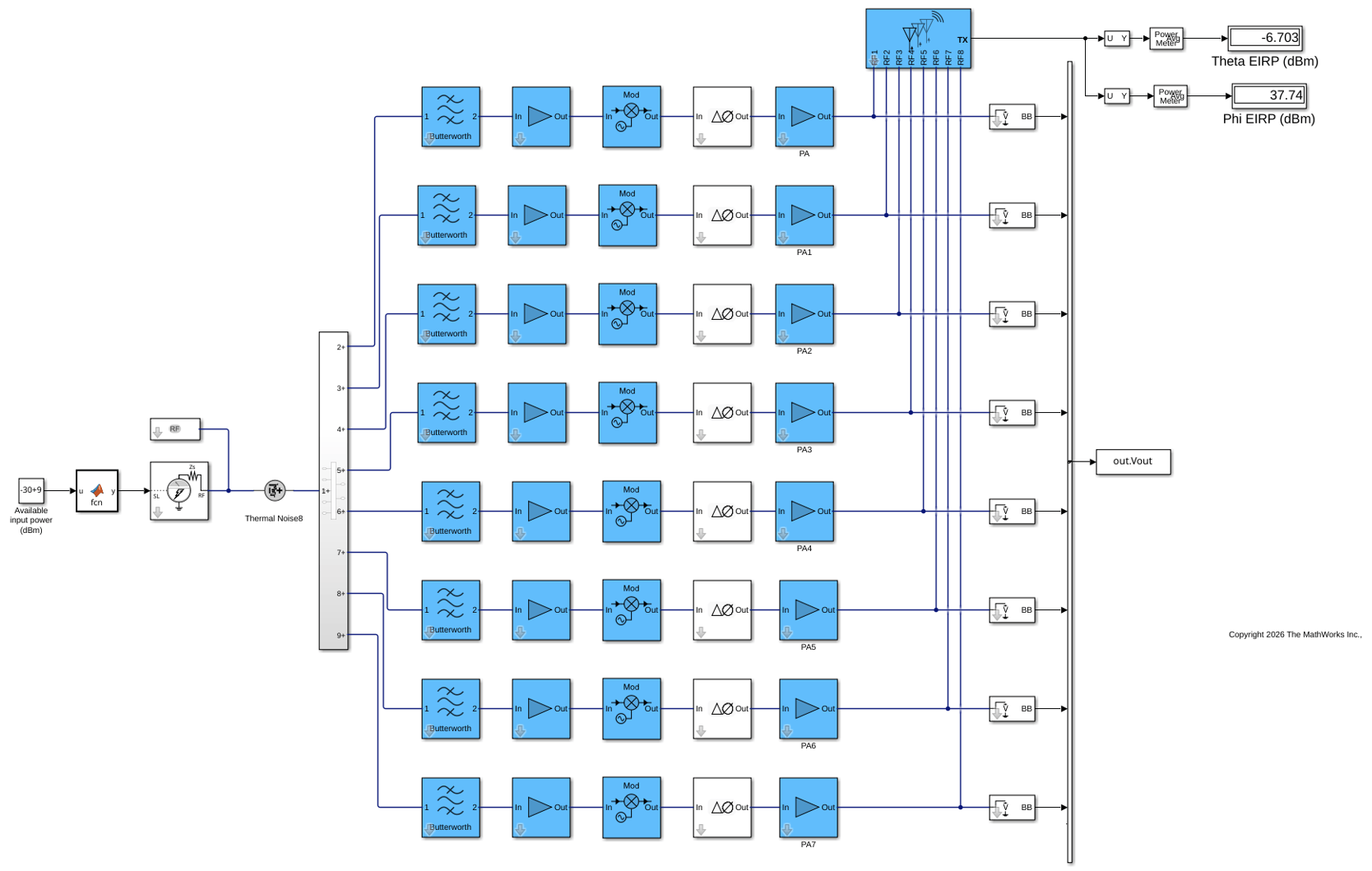
To distribute a single input signal to the 8 radio frequency (RF) chains, add a corporate power divider at the transmitter input. Start with an ideal Wilkinson power splitter to verify the signal distribution.
The model loads antennaData.mat (providing patchArray for the Antenna block) and uses phaseShifts from the model workspace (configured in Step 3). The Divider block uses an ideal 8-port Wilkinson splitter with no external data dependency.
The divider introduces a loss of approximately 9 dB (~20*log10(8)), so the input power is increased for comparison with previous models.
open_system("TXmodel_5.slx");
sim("TXmodel_5.slx");
Design Corporate Power Divider at 4 GHz
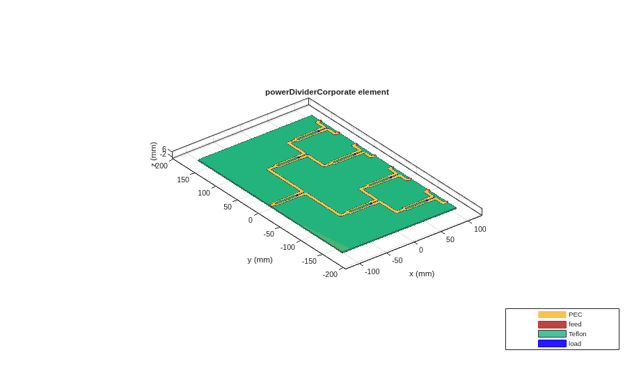
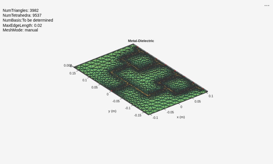
The power divider operates at the 4 GHz intermediate frequency (IF) because the signal is split before upconversion to 27 GHz. Design an 8-output corporate power divider at this frequency. Visualize the PCB geometry and mesh to confirm the layout before running EM analysis.
splitter = design(powerDividerCorporate(NumOutputPorts=8), 4e9);

figure;
show(splitter);

figure;
mesh(splitter, MaxEdgeLength=0.02)
Characterize Power Divider with EM Analysis
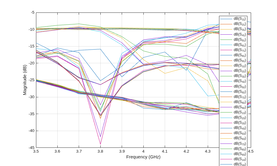
To capture the frequency-dependent behavior, extract the full 9-port (1 input + 8 outputs) S-parameter matrix using electromagnetic analysis. The full analysis takes approximately 15 minutes. Load the pre-computed results instead.
% f = linspace(3.5e9, 4.5e9, 11);
% sSplitter = sparameters(splitter, f);
% save("splitterData", "splitter", "sSplitter");

load("splitterData.mat");
Plot the S-parameters to verify the divider performance across the 3.5-4.5 GHz operating band.
figure;
rfplot(sSplitter)
Integrate EM-Characterized Divider into System-Level Simulation
To account for realistic PCB effects, replace the ideal divider with the EM-characterized S-parameters. The model loads splitterData.mat (providing sSplitter) in addition to antennaData.mat (providing patchArray). The S-parameters block in the power divider subsystem uses sSplitter to accurately model impedance mismatches, inter-port coupling, and frequency dispersion introduced by the PCB interconnect.
open_system("TXmodel_6pdiv.slx");
sim("TXmodel_6pdiv.slx");
Compare the output power between the ideal and EM-characterized divider models to observe the additional loss introduced by PCB effects.
See Also
Wireless Digital Video Broadcasting with RF Beamforming | Integrate Phase Shifter Into RF Receiver

