Use RF Measurement Testbench for RF-to-IQ Converter
Use the RF Measurement Testbench to measure various quantities
of an RF-to-IQ converter. Measurable quantities include cumulative
gain, noise figure, and nonlinearity (IP3) values. To open the testbench
and measure the quantities, use the RF Budget Analyzer app
to create an RF-to-IQ converter and then click Export > Measurement
testbench.
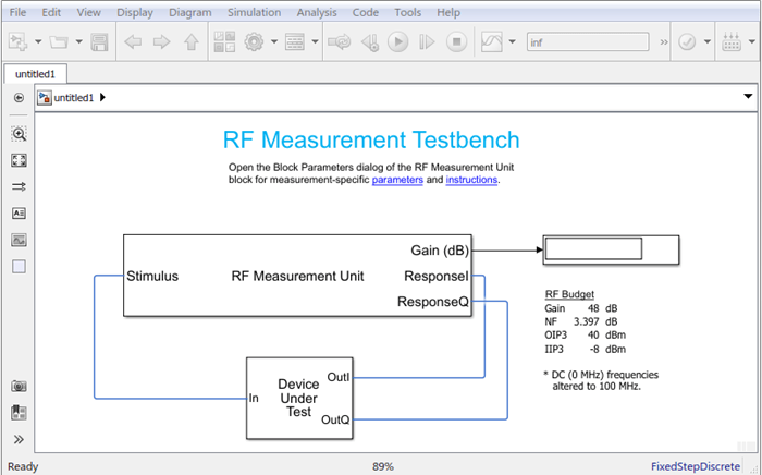
The testbench has two subsystems:
RF Measurement UnitDevice Under Test
The testbench display shows the measured output values of the gain, NF (noise figure), IP3 (third-order intercept), and other quantities etc.
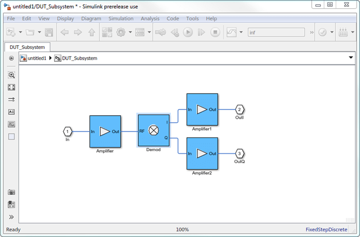
Device Under Test
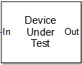
The Device Under Test subsystem contains the RF system exported from the app.
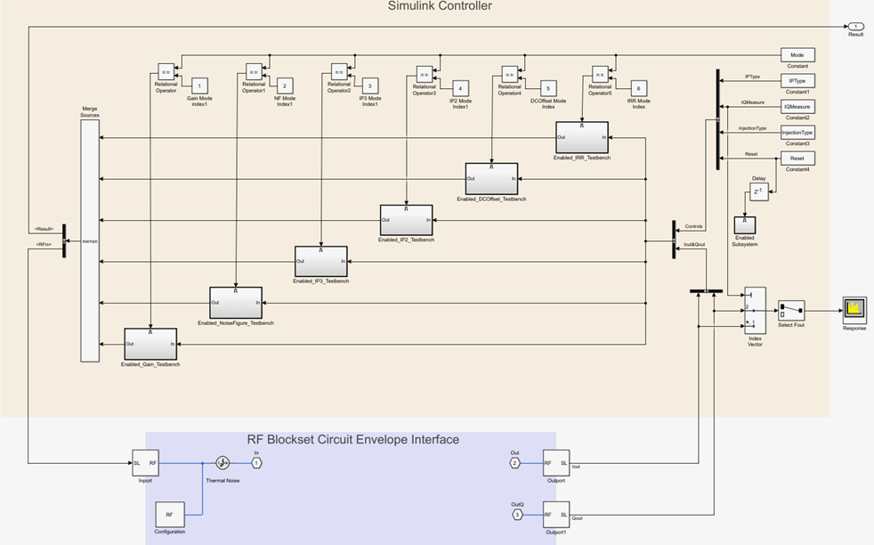
RF Measurement Unit
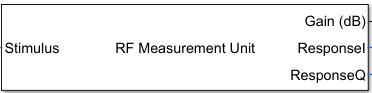
The RF Measurement Unit subsystem consists of a Simulink Controller and RF Blockset Circuit Envelope interface. The RF Blockset™ interface is used as input and output from the DUT.
RF Measurement Unit Parameters
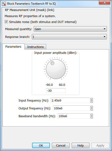
Simulate noise (both stimulus and DUT) — Select this check box to enable noise modeling in the stimulus signal entering the DUT and inside the DUT.
Measured quantity — Choose the quantity you want to measure:
Gain– Measure the transducer gain of the converter, assuming a load of 50 ohm. If you choose onlyIor onlyQfrom Response branch, you see only half the value of the measured gain.NF– Measure the noise figure value at the output of the converter.IP3– Measure the output or input third-order intercept (IP3).IP2– Measure the output or input second-order intercept (IP2).DC Offset– Measure the DC level interference centered on the desired signal due to LO leakage mixing with input signal.Image Rejection Ratio– Measure the image rejection ratio required to cancel the effect of images at the RF input signal.
By default, the testbench measures the
Gain. The contents in the Instructions tab changes according to the Measured quantity value.IP Type — Choose the type of intercept points (IP) to measure:
Output referredorInput referred.By default, the testbench measures
Output referred. This option is available when you set the Measured quantity toIP2orIP3.Injection Type – Choose the local oscillator (LO) injection for image rejection ratio:
Low-sideorHigh-side.By default, the testbench measures the
Low-side. This option is available when you set the Measured quantity toImage Rejection Ratio.Response branch — Choose the output branch you want to measure from:
I only(Q=0)– Output signal measured at the in-phase branch.Q only(I=0)– Output signal measured at the quadrature branch.
This option is not available when you set the Measured quantity to
Image
Rejection Ratio
.
Parameters Tab
Input power amplitude (dBm) – Available input power to the DUT. You can change the input power by manually specifying a value or by turning the knob. When measuring DC Offset, this input field is Input RMS voltage (dBmV), because the Offset is measured in voltage units. The specified voltage represents the voltage falling on the input ports of the DUT.
Input frequency (Hz) – Carrier frequency fed at the RF input of the DUT.
Output frequency (Hz) – Output frequency to measure the I and Q outputs of the DUT. By default, this frequency is one bandwidth above DC, to allow meaningful measurement.
Baseband bandwidth (Hz) – Bandwidth of the input signal.
Ratio of test tone frequency to baseband bandwidth – Position of the test tones used for IP3 measurements. By default, the value is
1/8.
Instructions Tab
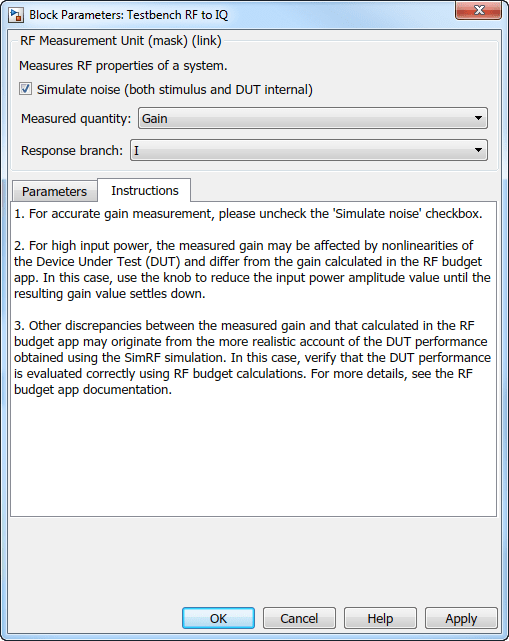
Instructions for Gain Measurement
Clear Simulate noise (both stimulus and DUT) for accurate gain measurement. Select the check box to account for the noise.
Change the Input power amplitude (dBm) or turn the knob to reduce the input power amplitude. For high input power, nonlinearities in the DUT can affect the gain measurements.
Instructions for NF Measurement
The testbench measures the spot NF calculated. This calculation assumes a frequency-independent system within a given bandwidth. To simulate a frequency-independent system and calculate the correct NF value, reduce the baseband bandwidth until this condition is fulfilled. In common RF systems, the bandwidth is reduced below 1 kHz for NF testing.
Change Input power amplitude (dBm) or turn the knob to reduce or increase the input power amplitude. For high input power, nonlinearities in the DUT can affect the NF measurements. For low input power, the signal is too close or below the noise floor of the system. As a result, the NF fails to converge.
Instructions for IP3 and IP2 Measurement
Clear Simulate noise (both stimulus and DUT) for accurate IP3 and IP2 measurement.
Change Input power amplitude (dBm) or turn the knob to reduce the input power amplitude. For high input power, higher-order nonlinearities in the DUT can affect the OIP3 and IIP3 measurements.
Instructions for DC Offset Measurement
Clear Simulate noise (both stimulus and DUT) for accurate DC offset measurement.
Correct calculation of the DC offset assumes a frequency-independent system in the frequencies surrounding the test tones. Reduce the frequency separation between the test tones or reduce the baseband bandwidth until this condition is fulfilled. In common RF systems, the bandwidth is reduced below
1 KHzfor DC offset testing.. Change Input RMS voltage amplitude (dBmV) or turn the knob to reduce the input RMS voltage amplitude. For high input RMS voltage, higher-order nonlinearities in the DUT can affect the DC offset measurements
Instructions for Image Rejection Ratio
Clear Simulate noise (both stimulus and DUT) for accurate OIP3 and IIP3 measurement.
Correct calculation of the image rejection ratio (IRR) assumes a frequency-independent system in the frequencies surrounding the test tones. Reduce the frequency separation between the test tones or reduce the baseband bandwidth until this condition is fulfilled. In common RF systems, the bandwidth is reduced below
1 KHzfor IRR testing.. Change Input power amplitude (dBm) or turn the knob to reduce the input power amplitude. For high input power, higher-order nonlinearities in the DUT can affect the image rejection ratio measurement.
For all measurements using the testbench, you cannot correct result discrepancies using the RF Budget Analyzer app. The RF Blockset testbench provides true RF circuit simulation that incorporates RF phenomena including saturation and interaction between multiple tones and harmonics in nonlinear devices. These RF phenomena are not yet incorporated in RF Budget Analyzer, leading to some differences in the values between the testbench and the app.
See Also
RF Budget Analyzer | Amplifier | Mixer