Cam and Follower (AB-PB)

Libraries:
Simscape /
Foundation Library /
Mechanisms
Description
The Cam and Follower (AB-PB) block represents a cam and follower mechanism in position-and-angle-based mechanical systems. The cam rotates in an angle-based rotational network and the cam follower travels back and forth in a position-based translational network. The cam axle coincides with the rotational network axis. The cam applies a normal force on the follower. The normal force is perpendicular to the cam surface at the contact point with the follower.
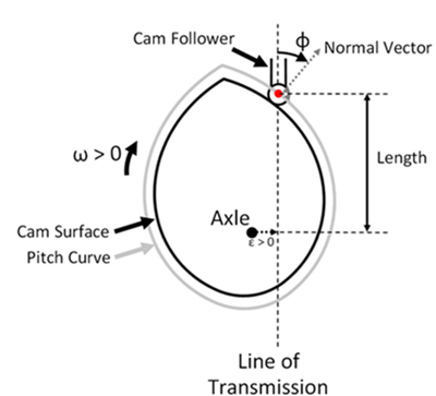
To define the cam profile, you provide a vector of cam angles and a vector of corresponding lengths, and the block performs a table lookup on these values during simulation. Each length value represents the distance between axle and follower, along the line of transmission, at a given cam angle. This length corresponds to the distance between the translational ports of the follower, Bt and Ft,
The block models the relative port velocities of the cam and follower as
where:
Length is the distance between axle and follower at a given cam angle.
θ is the cam angle.
ω is the cam angular velocity.
vBt and vFt are the absolute velocities of ports Bt and Ft, respectively.
xBt and xFt are the absolute positions of ports Bt and Ft, respectively.
The block uses the central difference theorem to numerically approximate a vector of values from the angle and length vectors, θTLU and LengthTLU, with an angle wrap from 0 to 2π. Then, during simulation, the block performs a table lookup with smooth interpolation on the specified values, also with an angle wrap from 0 to 2π
where is the derivative of length with respect to angle.
Using the table lookup with smooth interpolation, instead of directly implementing the equation that relates angular and translational velocities of the cam and follower, results in smooth relative acceleration between ports Bt and Ft, but it may cause numerical drift in some models. You can decrease the drift by increasing the number of elements in the angle and length vectors, θTLU and LengthTLU. Because of angle wrap in the table grid, select the last element of the θTLU vector so that it is close to a multiple of 2π.
The angle from the line of transmission to the cam normal direction is the pressure angle, Φ. A pressure angle of 0 degrees has 100% of force transmitted from the cam to the follower translation. A pressure angle of 90 degrees has 0% force transmitted from the cam to the follower translation. The block tracks the pressure angle as an intermediate.
The force-torque relationship is
where:
t is the torque of the rotational network acting on the cam axle.
f is the force of port Bt acting on port Ft.
Φ is the pressure angle.
ε is the eccentricity.
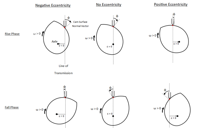
Eccentricity is the offset between the cam axle and the line of transmission. For positive angular velocity, a positive value of eccentricity decreases the pressure angle in the rise phase and increases the pressure angle in the fall phase. Negative eccentricity does the reverse. This schematic illustrates the effect of eccentricity and phase on pressure angle.
The relationship between Length and the cam pitch curve is
where Rp is the radius of the pitch curve.
Variables
To set the priority and initial target values for the block variables prior to simulation, use the Initial Targets section in the block dialog box or Property Inspector. For more information, see Set Priority and Initial Target for Block Variables.
Nominal values provide a way to specify the expected magnitude of a variable in a model. Using system scaling based on nominal values increases the simulation robustness. Nominal values can come from different sources, one of which is the Nominal Values section in the block dialog box or Property Inspector. For more information, see Modify Nominal Values for a Block Variable.
Examples
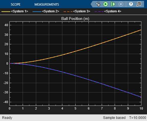
Interfacing Angle-Based Rotational and Position-Based Translational Networks
Demonstrates how you can define positive directions for translation and rotation in your physical view and adjust the Simscape™ network to achieve the desired behavior. It highlights the flexibility of Simscape in mapping physical directions to schematic representations.
Ports
Conserving
Parameters
Geometry
Vector of cam angle values.
Vector of lengths corresponding to the cam angle vector values. Each length value represents the translational distance between axle and follower at a specific cam angle. This vector must be of the same size as the Angle vector.
Offset between the cam axle and the line of transmission. For positive angular velocity, a positive value of eccentricity decreases the pressure angle on the rise but increases the pressure angle on the fall. Negative eccentricity does the reverse.
Check whether there is a tensile force (f < 0) between the cam and follower during simulation. A tensile force is not physically possible for a typical knife-edge or roller follower, therefore a tensile force indicates an issue with the model.
None― The block does not report if there is a tensile contact force during simulation.Warning― The block issues a warning, but continues the simulation.Error― The block returns an error and stops the simulation.
Ports
To improve block diagram readability, specify the rotational ports to display. The two rotational ports are rigidly attached to each other, so the effect is purely graphical and the block functions exactly the same whether it has one or two ports. Select the rotational ports visible on the block icon:
Br and Fr— Expose both ports, Br and Fr.Br— Expose only port Br.Fr— Expose only port Fr.
To improve block diagram readability, specify which of the translational ports follows the cam profile. The effect is purely graphical. Select the translational port to use:
Ft— Attach port Ft to the cam profile.
Bt— Attach port Bt to the cam profile.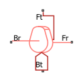
References
[1] Norton, Robert L., and Jianyou Han. Design of machinery. Higher Education Press, 2007.
Extended Capabilities
Version History
Introduced in R2026a