系统和模型
本主题中的概念为使用 Simulink® 软件工具提供一致且通用的语言。
系统
系统是一组相互依赖的物理和功能部件,具有随时间变化的可测量特性。
例如,车辆是一个具有多个部件的系统。可测量特性包括车辆的线性速度和车轮的转速。

系统组件
系统组件是系统的一部分,它与系统的其他部分交互。组件之间的交互定义系统的结构和行为。
例如,巡航控制模块是车辆系统中的一个系统组件。微控制器及其相关联的硬件定义结构,而控制速度的软件算法定义行为。

模型
模型是对从物理定律或试验数据派生的系统的数学描述。该描述通常使用一组变量以及一组定义各变量之间关系的微分和差分方程。
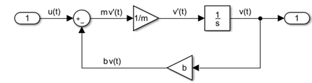
在以下车辆示例中,u(t) 是使车辆前进的力 (N),v(t) 是速度 (m/s),b 是阻力系数 (Nׂׂ·s/m),m 是车辆的质量 (kg)。

车辆是连续系统。对于连续系统,微分方程描述变量的变化率,为所有时间值都定义方程。车辆的速度 v(t) 及其加速度 v'(t) 由以下一阶微分方程定义。

mv'(t) + bv(t) = u(t)
您可以通过添加模块、指定模块行为并使用信号线将模块相互连接来为此方程创建一个 Simulink 模型。以下 Simulink 模块图实现该微分方程。
模型组件
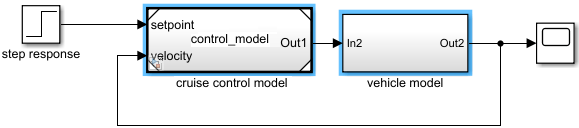
模型组件是模型的一部分,它通过输入和输出接口与其他部分交互。Simulink 使用 Subsystem 和 Model 模块实现模型组件。一个 Model 模块引用保存在单独文件中的另一个 Simulink 模型。
在以下示例中,控制模型保存在 Simulink 模型文件 control_model.slx 中,然后从另一个 Simulink 模型中的 Model 模块引用该控制模型。添加了 Subsystem 模块以用于对车辆机械进行建模。
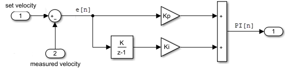
通常,控制器使用离散系统构建,使用计算机实现控制算法。对于离散系统,差分方程描述只在特定时间定义的变量的变化率。例如,简单离散 PI(比例-积分)控制器的控制信号可以用以下差分方程定义。
PI[n] = e[n]Kp + (e[n]+integral[n-1])Ki
其中 e[n] 是受控信号值(速度)与指定值(设定速度)之间的误差,Kp 是比例常数,Ki 是积分常数,n 是时间步。
以下 Simulink 模块图实现该差分方程。
微分代数方程
除了微分方程外,有些方程组还包含涉及自变量和状态向量的其他约束。此类方程组称为微分代数方程 (DAE)。
代数一词是指不涉及任何导数的方程。
在 Simulink 模型中,代数环表示代数约束。具有代数环的模型定义微分代数方程组。
以一个实现简单 DAE 方程组的模型为例。内环表示代数约束,而外环表示微分方程。
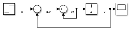
此模型实现以下 DAE 方程组。
x' = xa
0 = u - x - 2xa