Main Content

Model Reference Basics

As your models increase in size and complexity, you can create and reference other models that represent pieces of your design. Each model should have a well-defined scope and perform functionality defined by requirements.

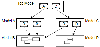
To include one model in another, use a Model block. Each Model block is a model reference, or a reference to another model. Each model is saved in a separate model file. You can reference the same model multiple times in a model hierarchy, and multiple models can reference the same model. These references create a model hierarchy.

A top model references model A, which references model B twice. The top model also references model C, which references models B and D.

A model can function as both a referenced model and a standalone model without changing the model or the entities derived from the model.

By referencing models, you:

  • Enable modular development, which lets you, your team members, and third parties develop the models within the hierarchy simultaneously.

  • Benefit from incremental behavior, which speeds up model loading and can accelerate simulation and code generation.

  • Provide isolated environments for testing and verifying the behavior of components in the model hierarchy.

  • Encapsulate a piece of your design in a way that allows for easy sharing with or without intellectual property protection.

To compare model references, subsystem references, subsystems, and libraries, see Explore Types of Model Components.

Model Reference Hierarchy

A model hierarchy can use multiple componentization techniques. For example, a model can use a combination of subsystems, referenced models, and Stateflow® charts to create hierarchy.

When a model hierarchy contains referenced models, the top model is the top-level model in the Simulink® window.

Suppose you open the sldemo_mdlref_basic model. Then, you navigate into a referenced model via the Model block named CounterA.

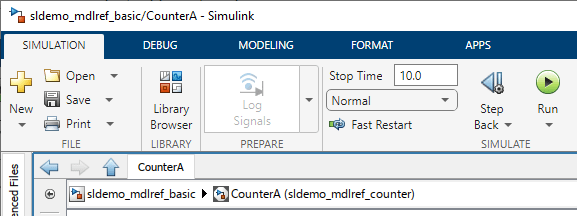
The window title includes two elements:

  • sldemo_mdlref_basic — Name of the top model

  • CounterA — Name of the Model block

Simulink window titled sldemo_mdlref_basic/CounterA

The Explorer Bar includes three elements:

  • sldemo_mdlref_basic — Name of the top model

  • CounterA — Name of the Model block

  • sldemo_mdlref_counter — Name of the referenced model

Explorer Bar displaying sldemo_mdlref_basic > CounterA (sldemo_mdlref_counter)

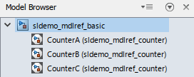
The Model Browser displays the hierarchy of the top model, referenced models, and other model components.

Model Browser for sldemo_mdlref_basic

A model can contain multiple Model blocks that reference the same model as long as the referenced model does not define global data. For example, the sldemo_mdlref_basic model contains three Model blocks that reference the sldemo_mdlref_counter model.

Three Model blocks display the name of the referenced model (sldemo_mdlref_counter) on their block icons.

The referenced model can also appear in other models at any level.

To prevent cyclic inheritance, a Model block cannot reference a model that is above it in the model hierarchy. For example, a model cannot reference its parent model, which is the model that references it.

A top model references model A, which references model B. The referenced models, model A and model B, cannot reference the top model. Model B also cannot reference model A, which is its parent model.

To open a referenced model as a top model, on the Model block icon, click the Open As Top Model badge. The referenced model opens outside of the context of the current model hierarchy.

When you edit a model, the changes affect the same model file regardless of whether the model is open as a referenced model or top model.

Model Reference Interface

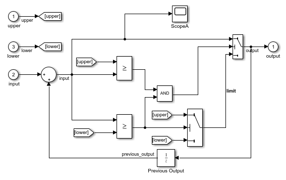
The ports on a Model block correspond to blocks at the top level of the referenced model. The ports can be input, output, or control ports.

In the sldemo_mdlref_basic model, each Model block references the sldemo_mdlref_counter model and has:

  • Three input ports, named upper, input, and lower

  • One output port, named output

Each Model block receives three input signals and returns one output signal.

The sldemo_mdlref_counter referenced model has:

  • Three Inport blocks, named upper, lower, and input

  • One Outport block, named output

Blocks that represent model input and output are part of the block diagram for the model.

When you connect a signal to a Model block port, you connect the signal to the corresponding port of the referenced model. The output of a Model block can differ despite the referenced model being the same.

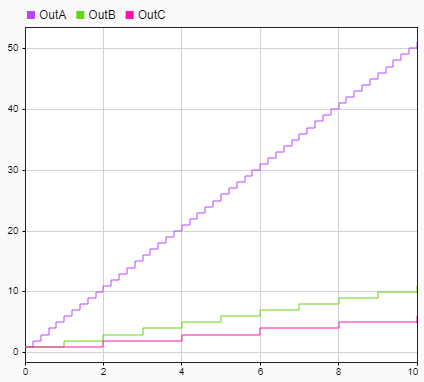
In sldemo_mdlref_basic, each Model block port named input receives a signal from a unique Pulse Generator block. Because the input signal from each Pulse Generator block uses a different sample time, the output signal from each Model block differs despite the referenced model being the same.

To view how the output signal for each Model block differs, you can use the Simulation Data Inspector.

Simulation Data Inspector plot of the output signal for each model instance

Signal attributes in the referenced model are independent from the context of the Model block. For example, signal dimensions and data types do not propagate across the Model block boundary. To define signal attributes in the referenced model, use the block parameters of the root-level Inport and In Bus Element blocks.

Model Reference File Management

Each model reference is a reference to a model file. Model references support collaboration with team members and third parties. For example, model references can help you satisfy these requirements:

  • Modular development — You can develop a referenced model independent from the models that use it. You can open a referenced model without the context of a model hierarchy. Then, you can simulate and generate code for the referenced model. A referenced model is a standalone component that you can use in an assembly and integrate with other components.

  • Incremental loading — When you load the top model in a model hierarchy, the software speeds up the loading process by loading only the top model. The software loads each referenced model when each model is needed. For example, when you compile the model hierarchy, the software loads each referenced model.

  • Intellectual property protection (with a Simulink Coder™ or HDL Coder™ license) — You can obscure the contents of a referenced model, allowing you to distribute the model as a protected model without revealing its intellectual property. You can grant the protected model recipient permission to view, simulate, and generate code for the protected model. For more information, see Protect Models to Conceal Contents (Simulink Coder) or Create Protected Models to Conceal Contents and Generate HDL Code (HDL Coder).

Model Reference Data Storage

Model references support multiple data storage options. For example, consider these features:

  • Model workspace — Each model has its own model workspace for storing variable values. In a model hierarchy, each model workspace acts as a unique namespace. Therefore, you can use the same variable name in multiple model workspaces.

  • Data dictionary — To share data among models, use a data dictionary. A data dictionary is a standalone file that permanently stores data. Similar to a header file, a data dictionary provides a location outside of the model that can store and share data definitions.

Duplicate data definitions can exist in a model reference hierarchy under these conditions:

  • Each model in the hierarchy sees only one definition.

  • Definitions are the same across the model hierarchy.

A referenced model can depend on data from a higher-level model. When you open a referenced model as a standalone top model, provide the required data.

To decide how to store data for your models, see Determine Where to Store Variables and Objects for Simulink Models.

Model Reference Behavior and Execution

During simulation and code generation, a Model block behaves like a single block, or atomic unit. When the Model block executes, the blocks within the referenced model execute the current task without interruption from blocks in the parent system.

Each referenced model compiles independently. This standalone behavior can improve the performance of your model hierarchy and help you achieve your modeling goals.

To modify how a referenced model behaves and when it executes, consider these features:

  • Independent configuration sets — The configuration set used by a referenced model can differ from the configuration set of its parent or other referenced models. For more information, see Set Configuration Parameters for Model Hierarchies.

  • Instance parameters — By default, a block parameter has the same value in each Model block instance of a reusable referenced model. To specify a different block parameter value for each instance of a reusable referenced model, create model arguments. For example, if you add a Gain block to model sldemo_mdlref_counter, model arguments allow each of the three instances of this model to use different gain values. See Configure Instance-Specific Values for Block Parameters in a Referenced Model.

  • Model masks — With a model mask, you can control the appearance of Model blocks and customize the way the blocks display model arguments. For model mask requirements, see Model Masks.

  • Conditional execution — An external signal can control whether a Model block executes during simulation. For more information, see Conditionally Execute Referenced Models.

  • Dynamic startup and shutdown behavior — To model dynamic startup and shutdown behavior for a Model block, add custom routines to the default initialization and termination routines of the Model block. For more information, see Using Initialize, Reinitialize, Reset, and Terminate Functions.

  • Variants — You can use multiple Model blocks to represent multiple design variations of a system component. A conditional expression determines the active variant. For more information, see What Are Variants and When to Use Them.

Model Reference Simulation and Code Generation

When you simulate a model hierarchy, the top model simulates.

Suppose you open the sldemo_mdlref_basic model. Then, you navigate into a referenced model via the Model block named CounterA.

Window with sldemo_mdlref_counter open as referenced model

The sldemo_mdlref_basic model is the top model. When you click Run, the sldemo_mdlref_basic model simulates.

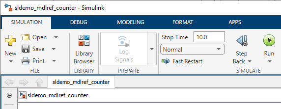
Suppose you open the sldemo_mdlref_counter model as a top model in a new window.

Window with sldemo_mdlref_counter open as top model

In the new window, the sldemo_mdlref_counter model is the top model. When you click Run, the sldemo_mdlref_counter model simulates.

For a referenced model to simulate as a standalone top model, the referenced model must have the data required to execute in a standalone context. For example, the referenced model must have the variables and data types that define parameters and signals.

When your component is reused multiple times in a model hierarchy and contains many blocks, implementing the component as a model reference can speed up simulation and code generation. For example, when you use model references, you can benefit from:

  • Accelerated simulation — When a referenced model simulates in accelerator mode, the software converts the referenced model to code. Then, the software simulates the model by running the code, which is faster than simulating the referenced model interpretively (in normal mode). To compare the simulation mode tradeoffs, see Choose Simulation Modes for Model Hierarchies.

  • Incremental builds — The software generates code for a referenced model only if the model has changed since the code was previously generated. When your team members or a continuous integration system generate code for referenced models, Simulink cache files package this code for reuse. Using local copies of these files can speed up simulation and code generation. For information about generating code for a model reference hierarchy, see Generate Code for Model Reference Hierarchy (Simulink Coder).

  • Cached build artifacts — Simulink cache files contain build artifacts that can speed up simulation and code generation. For more information, see Share Simulink Cache Files for Faster Simulation and Simulink Cache Files for Incremental Code Generation (Simulink Coder).

  • Local solvers (since R2022a) — When you use a local solver in a referenced model, the software solves a model reference as a separate set of differential equations. The local solver can use a different, smaller (since R2024a) or larger step size. The choice of solver and solver settings involves a trade off between speed and accuracy in simulation. For more information, see Use Local Solvers in Referenced Models.

  • Parallel computing (with a Parallel Computing Toolbox™ license) — For large model reference hierarchies, you can increase the speed of diagram updates by building model reference targets in parallel. For a referenced model to build in parallel, you must configure it to run in accelerator mode. For more information, see Reduce Update Time for Referenced Models by Using Parallel Builds.

Model Reference Testing and Verification

Model references help you verify the behavior of your component by offering an isolated environment. For example, model references support your testing and certification requirements with:

  • Unit testing — You can test a referenced model independently by simulating the referenced model as a top model, isolating its behavior. You can also create a test harness that exercises the referenced model in a test environment with various test scenarios. Unit testing can eliminate retesting for unchanged components and reduce the cost of verification. For more information, see Component Verification. For help verifying compliance with industry standards and guidelines, see Check Your Model Using the Model Advisor.

  • SIL/PIL testing (with an Embedded Coder® license) — To verify referenced models in an environment that mimics the target environment, you can simulate the referenced models in software-in-the-loop (SIL) or processor-in-the-loop (PIL) mode. These simulations let you generate and test production code that is compiled for and executed on the host platform for SIL simulations and the target platform for PIL simulations. For more information, see SIL and PIL Simulations (Embedded Coder).

  • Single-sourced generated code — Each referenced model has one set of source code, regardless of how many times a model hierarchy includes the referenced model. Single-sourced code can reduce the cost of verification.

  • Independent traceability for generated code — You can trace the generated code for a referenced model independently of other models. Suppose you confirm that the generated code traces back to the referenced model with baseline equivalence tests and additional test vectors that target 100% code coverage. Changes to the parent model do not affect this verification testing, which reduces the cost of verification.

    With a Simulink Code Inspector™ license, you can create a traceability matrix for each referenced model. The traceability matrix provides the traceability among model objects, generated code, and model requirements. For more information, see Generate Traceability Matrices (Simulink Code Inspector).

See Also

Related Topics