OV2640 Camera Sensor
Capture JPEG images using ArduCam 2MP Mini Plus camera module with OV2640 sensor
Since R2023b
Libraries:
Simulink Support Package for Arduino Hardware /
Sensors
Description
Add-On Required: This feature requires the Simulink Support Package for Arduino Hardware add-on.
The OV2640 Camera Sensor block captures images in the JPEG format using the ArduCam Mini 2MP Plus camera module with an OV2640 sensor. The camera is attached to an Arduino® board. This block is a composite sensor block and uses both the SPI and I2C modules.
For a list of boards that support the OV2640 Camera Sensor block, see Supported Boards.
Note
You cannot add multiple OV2640 Camera Sensor blocks to a model.
Supported Boards
This list shows the supported board and the corresponding image resolutions.
| Arduino Board | Supported resolutions |
|---|---|
| Arduino Mega 2560a | 160x120, 176x144,
320x240 |
| Arduino Mega ADK | 160x120, 176x144,
320x240 |
| Arduino Due | 160x120, 176x144,
320x240 |
| Arduino MKR1000 | 160x120, 176x144,
320x240, 352x288 |
| Arduino MKR WiFi1010 | 160x120, 176x144,
320x240, 352x288 |
| Arduino MKR Zero | 160x120, 176x144,
320x240, 352x288 |
| Arduino Nano 33 IoT | 160x120, 176x144 |
| Arduino Nano 33 BLE SENSE | 160x120, 176x144 |
ESP32-WROOM ESP32-WROVER | 160x120, 176x144,
320x240, 352x288,
640x480, 800x600, 1024x768,
1600x1200 |
a Arduino Mega 2560 board supports the | |
Note
To avoid memory overuse on the hardware, on the Hardware tab of the Simulink® model, in the Prepare section, select Control Panel. In the new window that opens, click the Signal & Triggering button. In the second window, clear the Send multiple contiguous samples in same packet option in the Configuration section and click OK.
Examples

Capture Images Using ArduCam OV2640 Camera Module and ESP32 Hardware
Capture JPEG images using the ArduCam OV2640 camera module with ESP32 hardware.
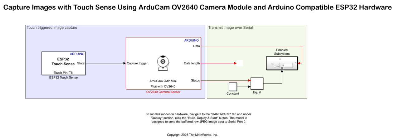
Capture Images with Touch Sense Using ArduCam OV2640 Camera Module and Arduino Compatible ESP32 Hardware
Design a touch-based image capture system using an Arduino ESP32 hardware and ArduCam OV2640 camera module. The example uses the ESP32 Touch Sense block from the Simulink® Support Package for Arduino® Hardware.
Ports
Input
Output
Parameters
Version History
Introduced in R2023b