Prepare, Configure, and Run Simulink Model for Different User Workflows on Arduino
This example shows how to use the Simulink® Support Package for Arduino® Hardware to prepare, configure, and run a Simulink model for different workflows such as PIL simulation, Connected IO, Monitor and Tune External mode, real-time code profiling, and deployment.
Hardware Setup
Connect your Arduino hardware board to the development computer. This example uses the Arduino Mega 2560 hardware board.
Configure Simulink Model
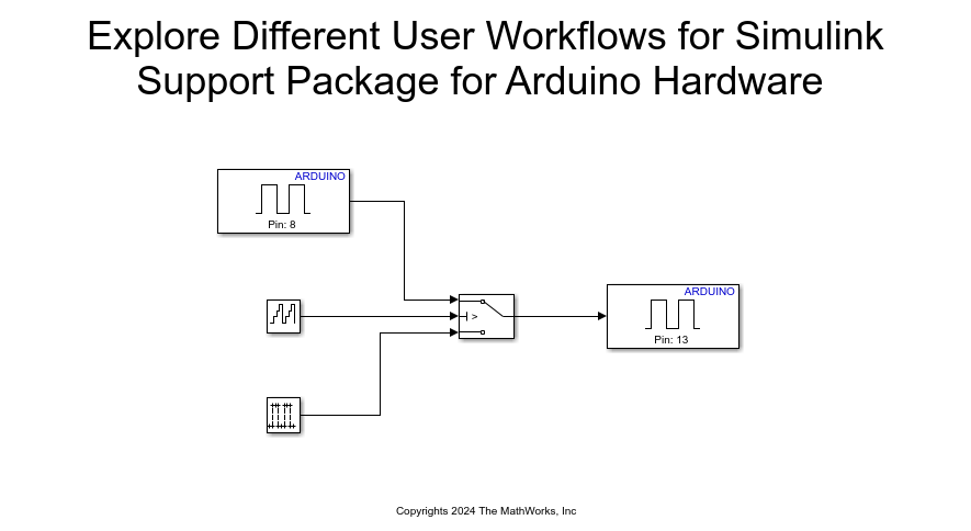
This example uses a preconfigured Simulink model from the Simulink Support Package for Arduino Hardware. In the Simulink model, the switch passes the input signal from the Digital Input block for the values less than the threshold you mention the Threshold parameter of the Switch block. For any values greater than the threshold, the Switch passes the input from the Pulse Generator. The example uses the Arduino on-board LED on pin number 13. In the Digital Output block, set Pin number to 13.
Open the arduinoUserWorkflows Simulink model.

1. In the Simulink Editor, select Simulation > Model Configuration Parameters.
2. In the Configuration Parameters dialog box, click Hardware Implementation.
3. Set the Hardware board parameter to Arduino Mega 2560 and click Apply. The parameter values under Hardware board settings are automatically populated to their default values. You can use any Arduino hardware with ARM® processor for this example.
Connected IO
Use Connected IO mode to communicate with the IO peripherals on the Arduino hardware board. This mode enables you to modify your model design and monitor the effect of the modified design using peripheral data from the Arduino hardware in a near real-time environment. For more information on how Connected IO works, see How Connected IO Works.
In the arduinoUserWorkflows Simulink model, the Digital Input and Digital Output blocks request peripheral data from the IO server. The IO server accepts the requests and responds with the data requested. Using this output peripheral data, you can verify that your model design meets the requirements.
For data acquisition, you can preconfigure the IO server to send data at a specific rate. Data acquisition can be done with Connected IO using these methods: polling, streaming, or automatic. For more information, see Data Acquisition using Connected IO.
Configure these parameters in the Configuration Parameters dialog box of the arduinoUserWorkflows Simulink model.
1. In Target hardware resources, from the Connected IO group, select the type of data acquisition for the Connected IO mode. For more information, see Connected IO Modes: Auto, Polling, and Streaming.
2. From the Host-board connection group, in the Connected I/O communication section, set the communication properties. For more information, see Host-board connection.
3. Click OK to close the dialog box.
4. On the Hardware tab of the model, in the Mode section, select Connected IO, and then click Run with IO.

5. You can change the rate of simulation by enabling simulation pacing. For more information, see Simulation Pacing Options.

Build Option
The build option defines how Simulink Coder™ responds when you press Ctrl+B or click Build to build your Simulink model.
The Build option:
Generates C-code from your Simulink model
Compiles and links the code into an executable with libraries
Simply building does not load and run the executable on the Arduino hardware boards.
Configure these parameters in the Configuration Parameters dialog box of the arduinoUserWorkflows Simulink model.
1. In Target hardware resources, from the Build options group, select a Build option from the drop down list and click Apply. For more information, see Build Options.
2. Click OK to close the dialog box.

3. To build your Simulink model, press Ctrl+B or click Build on the model toolbar.

External Mode Over Serial Communication
Use Monitor and Tune (External Mode) to tune parameters and monitor a Simulink model running on your Arduino hardware. Monitor and Tune enables you to tune model parameters and evaluate the effects of different parameter values on model results in real-time. When you change parameter values in a model, the modified parameter values are communicated to the Arduino hardware immediately. You can monitor the effects of different parameter values by viewing the output signals on the Digital Output block or in Analyze Simulation Results. This helps you find optimum values for performance and is called parameter tuning. For more information, see How Monitor and Tune Works.
Configure these parameters in the Configuration Parameters dialog box of the arduinoUserWorkflows Simulink model.
1. In Target hardware resources, from the Host-board connection group, in the External mode over serial communication section, set the communication properties. For more information, see Host-board connection.
2. From the External mode group, set Communication interface to XCP on Serial. For more information, see External mode.
3. Click OK to close the dialog box.
4. On the Hardware tab of the Simulink model, in the Run on Hardware section, set Stop Time to inf.
5. Click Monitor & Tune to start the process. The software
a. Builds the target application on your development computer.
b. Deploys the target application to the Arduino hardware.
c. Connects Simulink to the target application that runs on your Arduino hardware.
d. Starts execution of generated code on your Arduino hardware.
6. To perform the steps separately, under Monitor & Tune, click the following buttons under Step by Steps Commands. In this order,
a. Build for Monitoring
b. Deploy
c. Connect
d. Start
7. To stop the execution and disconnect the target application, in the Run on Hardware section of the Hardware tab, click Stop. To disconnect the target application from Simulink without stopping code execution, click the Stop drop-down menu and select Disconnect.
PIL Simulation
Use processor-in-the-loop (PIL) simulation to cross-compile source code on your development computer, and then download and run the object code on the processor in your Arduino hardware board. In PIL simulation, the code generated by software runs on the Arduino hardware board. The results of the PIL simulation are transferred to Simulink to verify the numerical equivalence of the simulation and the code generation results. PIL verification is a crucial part of the design cycle to ensure that the behavior of the deployment code matches the design. For more information, see SIL and PIL Simulations (Embedded Coder).
Top-Level PIL Simulation
In the top-level PIL simulation, code is generated for the top-level reference model and then deployed and executed on your Arduino hardware.
Configure these parameters in the Configuration Parameters dialog box of the arduinoUserWorkflows Simulink model.
1. In Target hardware resources, from the Host-board connection group, in the PIL communication section, set the communication properties. For more information, see Host-board connection.
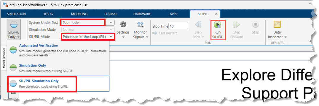
2. On the Apps tab, click SIL/PIL Manager.
3. In the Mode section, select SIL/PIL Simulation Only.
4. In the Prepare section, set System Under Test to Top model.
5. In the SIL/PIL Mode field, select Processor-in-the-Loop (PIL).
6. In the Run section, in the Stop Time field, specify simulation time.
7. Click Run SIL/PIL.

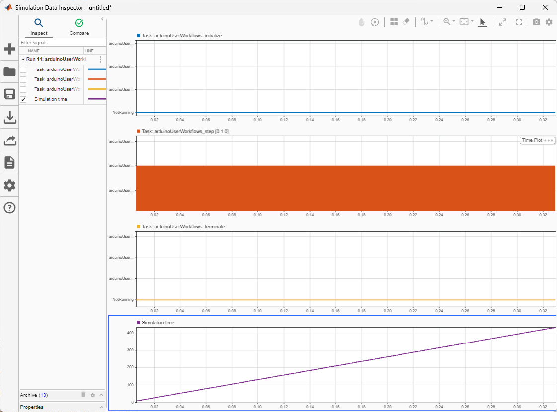
At the end of the simulation, in the Results section, click Data Inspector to view simulation results.
Real-Time Code Execution Profiling
Use the support package to profile the real-time execution of generated code running as an executable on Arduino hardware boards with XCP communication interface in External Mode. Sample time specified in the Simulink model determine the time schedule for running generated code on your Arduino hardware. With enough computing power on the hardware, the code runs in real-time according to the sample times you specify in the blocks. With real-time execution profiling, you can check if the generated code meets your real-time performance requirements.
Configure these parameters in the Configuration Parameters dialog box of the arduinoUserWorkflows Simulink model.
1. Go to Advanced Parameters and select Use Embedded Coder features.
2. In the left navigation pane of the Configuration Parameters dialog box, go to Code Generation > Verification. Select Measure task execution time to profile execution time for each rate in the Simulink model. The workspace variable, executionProfile, holds the profiling data in the workspace.
3. Set Save Options to All data.
4. Click OK to close the dialog box.
5. On the Hardware tab of the Simulink model, in the Run on Hardware section, set Stop Time to 5 seconds. Click Monitor & Tune to start the process. At the start of execution, a window appears and shows that the executable is running on your Arduino board. The code runs for 5 seconds and then stops.
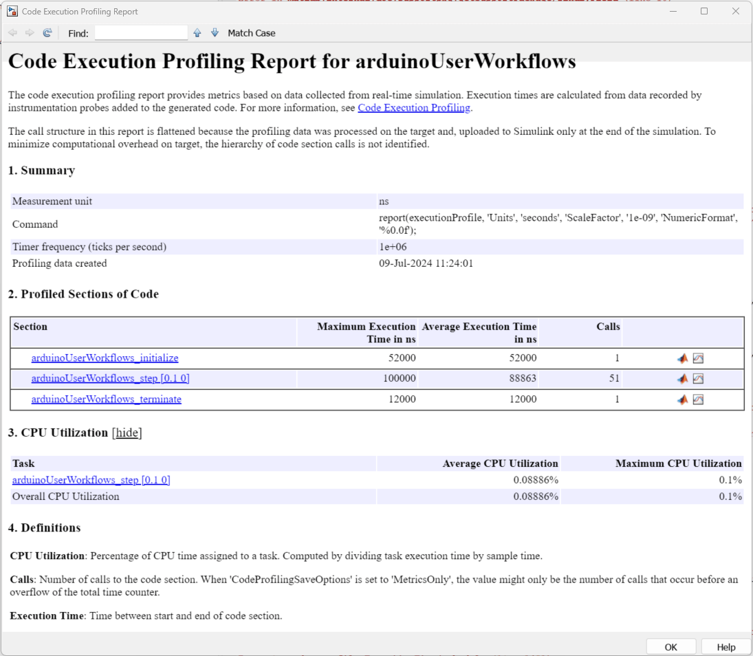
6. On the MATLAB® Command Window, execute this command to obtain the profiling report for the session that you just ran. This report shows each task has a different expected turnaround and execution time.
executionProfile.report

7. On the MATLAB Command Window, execute this command to visualize the scheduling of different tasks and functions. Notice where the faster task pre-empts the slower one and where different functions start and end.
executionProfile.schedule

Build, Deploy & Start
Build the Simulink model, generate a standalone executable, and start the application on your Arduino hardware. With Simulink Coder™ you can generate code for your Simulink model and deploy it to run as a standalone application on your Arduino hardware. This application continues to run even if the hardware is disconnected from your development computer.
Configure these parameters in the Configuration Parameters dialog box of the arduinoUserWorkflows Simulink model.
1. In the Target hardware resources, from the Host-board connection group, in the Application download section, set the communication properties. For more information, see Host-board connection.
2. Click OK to close the dialog box.
3. On the Hardware tab of the Simulink model, in the Mode section, select Run on board, and then click Build, Deploy & Start.
