External Interrupts Workflow for Arduino
This topic helps you with the workflow for external interrupts in a Simulink® model. To get started, perform these steps.
Create or open a Simulink model.
Add an External Interrupt block to the Simulink model.
Double-click the External Interrupt block to open the block parameters dialog box.
Specify the pin to which the interrupt has to be connected in the external interrupt block. For information on the pins that can be used in the block, click View Pinmap or see Pin Mapping for Arduino Timer-Independent Blocks.
Select the required option for Mode parameter.
RISING:This interrupt triggers when the pin voltage transitions from low to high voltage (0V to a positive voltage).FALLING:This interrupt triggers when the pin voltage transitions from high to low voltage (positive voltage to 0V).CHANGE:This interrupt triggers when the pin voltage is transitioning from low to high voltage.HIGH:This interrupt triggers when the pin voltage maintains a specific high voltage.LOW:This interrupt triggers when the pin voltage maintains a specific low voltage.
Select Pull-Up Input Pin option, if required. This selection ensures a defined signal state, contributing to reliable interrupt handling. When dealing with Falling Edge-triggered interrupts, select this option.
Add a Function-Call Subsystem block in the Simulink model.
The logic to be executed on the interrupt trigger is placed inside the function call subsystem.
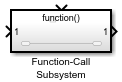
Connect the output of External Interrupt block to the Function Call input of Function-Call Subsystem block.
In the Simulink model, navigate to Modeling > Model Settings to open the Configuration Parameters dialog box.
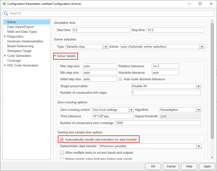
In the Configuration Parameters dialog box, navigate to Solver > Solver details and then select Automatically handle rate transition for data transfer option. Click Apply and OK.
Note
If block with interrupts are placed inside the Function-Call Subsystem block, then follow the steps mentioned in Workaround for Interrupt Workflow with Sensors.
See Also
Trigger Downstream Function-Call Subsystem Using Arduino External Interrupt Block