Workaround for Interrupt Workflow with Sensors
Workaround to call I2C functions from downstream function-call subsystem block in Arduino AVR targets
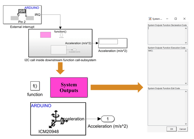
The Wire library of Arduino® AVR targets which is used for I2C communication is implemented using interrupts. When an interrupt occurs, the global interrupt enable, I-bit is cleared and all the interrupts are disabled. Since I2C is also based on interrupts, the I2C functions does not work inside downstream function-call subsystem.
The I2C calls inside the function-call subsystem will work if nested interrupts
are enabled. To enable nested interrupts, the sei() function must
be called inside the downstream function-call subsystem. This enables reading of I2C
functions from function-call subsystem.
The following example shows an ICM20948 block placed inside a downstream
function-call subsystem. For the I2C calls to work, a System Output block is placed
inside the downstream function-call subsystem. Sei() function is
added under System Outputs Function Execution Code to place the
sei() function inside the ISR of the generated code.

Workaround to reset interrupt pin of sensors supporting latched interrupts
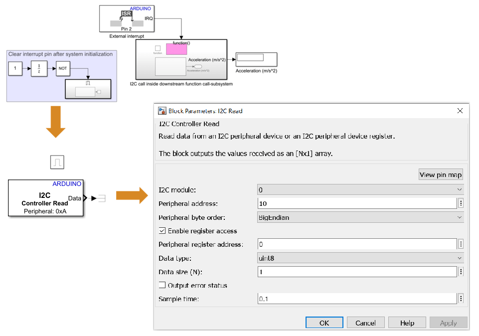
This topic helps you with the workaround to reset the interrupt pin of sensors which support latched interrupts. Sensor supporting latched interrupts provide register to reset the interrupt pin. The interrupt pin has to be reset after the system initialization. This ensures occurrence of continuous interrupts from the sensor. Use a model as shown in the image below to clear the interrupt pin of sensors that support latched interrupts.

The following table shows the peripheral address, reset interrupt pin register address, and data size for different sensors.
| Sensor | Peripheral Address | Reset Interrupt Pin Register Address | Data Size (uint8) |
|---|---|---|---|
| ADXL34x Accelerometer | 0x53 (default)| 0x1D | 0x32 | 6 |
| LIS3DH Accelerometer Sensor | 0x18 (default)| 0x19 | 0xA8 | 8 |