Get Started with Sensors for Robotics Applications Using Raspberry Pi and Simulink Online
This example shows how to use Simulink® Support Package for Raspberry Pi® Hardware and a Raspberry Pi hardware board to get started with the driver blocks for commonly used robotics sensors.
Introduction
Simulink Support Package for Raspberry Pi Hardware enables you to interface different sensors used in robotics applications by configuring the GPIO pins on the Raspberry Pi Hardware board. Various types of sensors are used in robotics applications for estimating the environmental conditions surrounding the robot. This example shows you three most widely used robotics sensors to get started with the robotics applications.
Color Sensor
The color sensors are used in robotics to detect the color of an object, a surface, or a path that the robot is supposed to follow. You can use the RGB color sensor such as TCS34725 to interface with Raspberry Pi Hardware board.
Ultrasonic Sensor
The ultrasonic sensors are used in robotics to estimate the distance from an object or obstacle which could be stationary, approaching or receding. You can use ultrasonic sensors such as HC SR04 to navigate the robot by measuring the distance from the objects in the surrounding environment.
Infra-Red Sensor
The Infra-Red (IR) sensors are used to measure distance to obstacles in robotics. The IR sensors have less power consumption compared to the ultrasonic sensors. You can use any IR sensor to navigate the robot.
This example shows you how to use the common robotics sensors like color, IR, and ultrasonic in robotics applications using Raspberry Pi Hardware board.
Prerequisites
Complete the Get Started with Simulink Support Package for Raspberry Pi Hardware and Connect to Raspberry Pi from Simulink Online examples.
Required Products
Simulink Online™
Simulink Support Package for Raspberry Pi Hardware
Required Hardware
To run this example, you will need the following hardware:
Raspberry Pi hardware board
Color or Ultrasonic or IR sensor
Hardware Setup
Connect the sensor to the Raspberry Pi hardware board.
Know the applications of different sensors used in robotics applications.
Choose the preferred robotic sensor and interface it with Raspberry Pi Hardware board.
You can use the I2C Controller Read block to read common I2C sensors.
Simulink Model
The Simulink online environment is functionally different from the desktop environment. If you open Simulink online, the below figure illustrates the view of its work environment.

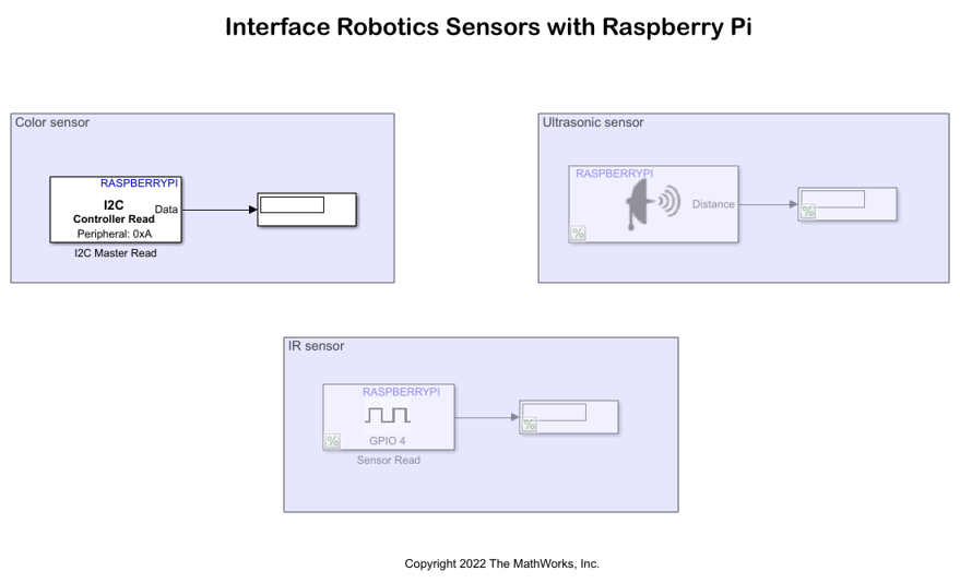
This example uses a preconfigured Simulink model from the Simulink Support Package for Raspberry Pi Hardware. The Simulink model consists of color, ultrasonic and IR sensor blocks, where you can choose the sensor subsystem as per the requirement and comment out the rest. For example, if you chose to use color sensor, interface color sensor to the Raspberry Pi Hardware board and comment out the ultrasonic and IR sensor blocks present in the Simulink model.
Open the raspberrypi_robotics_sensors_gettingstarted Simulink model.

The model is divided into three areas based on the blocks in each area.
Color sensor
You can choose the color sensor subsystem and comment out the rest if you choose to interface the Raspberry Pi Hardware with a color sensor. Color sensors are one of the common I2C sensors, hence the I2C Controller Read block is used to read data from the color sensor connected to hardware board through I2C interfacing.
Ultrasonic sensor
You can choose the ultrasonic sensor subsystem and comment out the rest if you choose to interface the Raspberry Pi Hardware with an ultrasonic sensor. The readily available Raspberry Pi ultrasonic sensor block is used in this model to represent the connection of ultrasonic sensor to the GPIO pin on the Raspberry Pi Hardware board.
IR sensor
You can choose the IR sensor subsystem and comment out the rest if you choose to interface the Raspberry Pi Hardware with an IR sensor. The GPIO read block is used in this model to represent the connection of IR sensor to the GPIO pin on the Raspberry Pi Hardware board.
Run Simulink Model in Connected IO Mode
You can run the model in connected IO mode where the model communicates with the hardware without any code generation in the hardware.
Follow these steps to run the Simulink model in connected IO mode.
1. Open the raspberrypi_robotics_sensors_gettingstarted Simulink model.
2. On the Modeling tab of the model, click Model Settings. In the Configuration Parameters dialog box, click Hardware Implementation on the left pane and set the Hardware board parameter to Raspberry Pi.
3. On the Hardware tab of the model, in the Mode section, click Run with IO.
4. Observe the captured sensor data in the display block of the sensor subsystem block.
Other Things to Try
Follow the steps in this example and replicate the workflow in desktop environment.
See Also
Get Started with Motor Drives for Robotics Applications Using Raspberry Pi and Simulink
Detect Stop Signal Traffic Sign Using Raspberry Pi and Simulink
Develop Path-Following Robot Using Raspberry Pi and Simulink
Develop Robot Navigation System Using Raspberry Pi and Simulink
Develop Obstacle Detection Robot Using ToF Sensor with Raspberry Pi