Create Print Frames for Printed Pages
Print frames are borders of a printed page that contain information about a block diagram, such as the model name or the date of printing. After you create a print frame, use the Simulink® or Stateflow® Editor to print a block diagram or chart with that print frame.
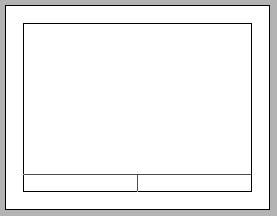
The default print frame has two rows:

Rows contain one or more cells. You can add content entries to cells. You can also add new rows and cells. Within cells, you can include text (such as the name and address of your organization) and variable content (such as the current date).
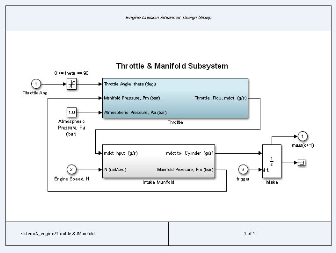
For example, the print frame below includes:
An additional row at the top of the frame for a title
A middle row, which includes the block diagram
A bottom row, in which one cell has the path to the subsystem and another cell has the page number

You can design a print frame for one particular block diagram, or you can design a more generic print frame for printing multiple block diagrams.
PrintFrame Editor
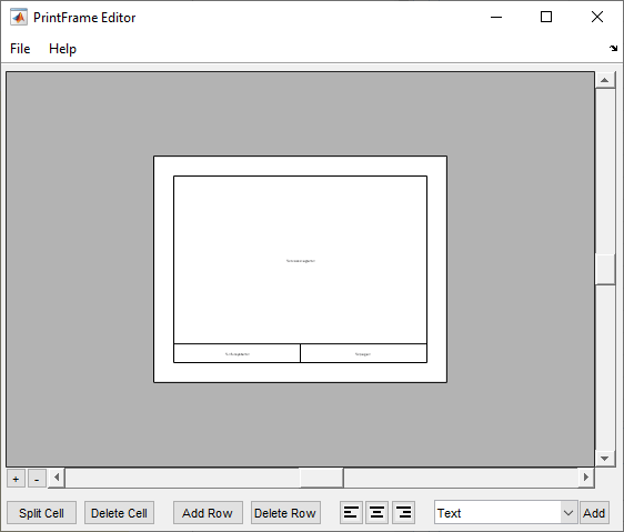
Use the PrintFrame Editor to create and edit print frames.
To open the PrintFrame Editor, at the MATLAB® Command Window, enter the frameedit command.

Use the PrintFrame Editor to:
Set up the printed page.
Add or remove rows and cells in the print frame.
Add content to cells, such as text, the date, and page numbers.
Format cell content.
To open an existing print frame, use frameedit with the
filename parameter, where filename is an
existing print frame (a .fig file).
Create a Print Frame
At the MATLAB prompt, type
frameeditto open the PrintFrame Editor.In the PrintFrame Editor, select File > Page Setup.
If necessary, change default page setup for the print frame, which is:
Paper type —
usletterOrientation — landscape
Note
The paper orientation you specify does not control the paper orientation used for printing. For example, assume you specify a landscape-oriented print frame in the PrintFrame Editor. If you want the printed page to have a landscape orientation, you must specify that using the Print Model dialog box.
Margins — 0.75 inches on all sides
Set up the layout of the print frame and add content.
Save the print frame as a
.figfile. Select File > Save As.
Add Rows and Cells to Print Frames
To add a row above the row that you select:
Click in a cell to select a row.
When you select a row, handles appear on all four corners. If you select only a line, handles appear on two corners.
Click Add Row.
The new row appears above the row that you selected.
To remove a row, select the row and click Delete Row.
To add cells within a row:
Select the cell that you want to split.
Click Split Cell.
The cell splits into two cells.
To remove a cell, select the cell and click Delete Cell.
To change the dimensions of a row or cell by selecting the bordering line:
Click the line you want to move.
A handle appears on both ends of the line.
Drag the line to resize the row or cell.
For example, to make a row taller, click the top line that forms the row. Drag the line up, and the height of the row increases.
Add Content to Print Frame Cells
You can add text, variables, or both to a cell.
To add content to print frame cells:
Select the cell that you want to add content to.
From the list, select the type of content that you want to add.
Click Add.
The type of content that you added appears in the cell.
Tip
If you click Add and nothing happens, it might be because you did not select a cell first.
If you add text, select the edit box and type in the text.
Tip
To make it easier to read and edit the content that you add, you can click the Zoom in + button.
To include multiple entries in a cell:
Select a cell that has a content entry.
Add another content type item from the list.
The new entry is added after the last entry in that cell.
Every print frame must include one Block Diagram
variable. If you do not specify a Block Diagram in one of
the cells, you cannot save the print frame and cannot print a block diagram with it.
In addition to the Block Diagram variable, you can add
other variables, such as the current date, to cells. Simulink supplies variable content at the time of printing.
The following table describes the variables you can add to cells.
| Variable Entries | Description |
|---|---|
Block Diagram | Add this variable in the cell in which you want the block diagram to print. You cannot include multiple
entries or text in the cell that contains the |
Date | The date that the block diagram and print frame are printed, in
dd-mmm-yyyy format. |
Time | The time that the block diagram and print frame are printed, in
hh:mm format. |
Page Number | The page of the block diagram being printed. |
Total Pages | The total number of pages being printed for the block diagram, which depends on the printing options specified. |
System Name | The name of the block diagram being printed. |
Full System Name | The name of the block diagram being printed, including its
position from the root system through the current system, for
example, engine/Throttle & Manifold. |
File Name | The file name of the block diagram, for example,
sldemo_engine.slx. |
Full File Name | The full path and file name for the block diagram, for example,
\\matlab\matlab\examples\simulink_automotive\main\sldemo_engine.slx. |
Text | The text that you want to include in that cell, for example, the name of your organization. To type additional text on a new line, press the Enter key. When you are finished editing, click outside of the edit box. You can copy and paste text from another document into a cell. Any formatting of the copied text is lost. To type special characters (for example,
superscripts and subscripts, Greek letters, and mathematical
symbols), use embedded TeX sequences. For a list of allowable
sequences, see the |
When you enter a variable, the cell displays the type of content in brackets,
<>, preceded by a percent sign, %.
For example, if you add a Page Number variable, it
appears as %<page>.
Note
Do not edit the text of a variable entry, because then the variable content
does not print. For example, if you accidentally remove the %
from the %<page> entry, the text
<page> prints instead of the actual page
number.
You can also add descriptive text to any of the variable entries without using the Text item.
Double-click in the cell.
Type text in the edit box before or after the entry.
To end editing mode, click outside of the cell.
Format Content in Cells
You can align cell contents using the left, center, and right alignment buttons.
Note
Block diagrams are always center aligned.
You can change font properties such as size or style (for example, italics or bold). To change font properties, select the cell, then right-click the contents and use the context menu to format the text.