Main Content

Save Signal Data Using Signal Logging

You can use signal logging to capture signal data from a simulation without adding blocks to your model. When signals are marked for logging, the software displays a logging badge . This example shows you how to use signal logging to log simulation data to the workspace and the Simulation Data Inspector.

To collect and use signal logging data:

You can also log subsets of marked signals. One approach for testing parts of a model as you develop it is to mark a superset of signals for logging and then override signal logging settings to select different subsets of signals for logging. You can use the Signal Logging Selector or a programmatic interface. For more information, see Override Signal Logging Settings.

For a summary of other approaches to capture simulation data, see Save Simulation Data.

Note

Saving a custom library block with signals marked for logging can result in logging unnecessary data and is not recommended. Instead, place a custom library block with no logged signals in the model. Then, mark signals for logging only for that instance of the library block.

Open Model

This example uses a model of a damped nonlinear spring given by the equation

x¨+x˙+k(x-a)+(x-a)3=0,

where:

  • a = 3 m is the resting length of the spring.

  • k = 1 N/m is the spring constant.

The model does not contain any Outport blocks and has no signals marked for logging. This example shows how to turn on signal logging and specify signal logging names.

The damped_nonlin_spring model

Enable Signal Logging for Model

By default, signal logging is enabled. With signal logging enabled, the software logs data during simulation for signals you mark for logging. You can enable or disable signal logging for a model using the Configuration Parameters dialog box. For example, check whether signal logging is enabled for the model damped_nonlin_spring.

  1. In the Modeling pane, select Model Settings.

  2. In the Data Import/Export tab, make sure the Signal logging parameter is selected.

Signal logging is enabled, so when you mark signals in the model for logging, the software logs the signal data during simulation. If the Signal logging parameter is not selected, the software does not log signals that are marked for signal logging.

You can also use the set_param function to enable or disable signal logging for a model programmatically.

set_param("damped_nonlin_spring",'SignalLogging','on')

Mark Signals for Logging

To analyze the damped nonlinear spring dynamics, mark signals for logging. The signal coming from the Integrator block named Integrator1 represents the position. The signal coming from the Integrator block named Integrator represents the velocity. To log signal data for the position and velocity of the spring, mark the signals for logging:

  1. Select the signals in the model.

  2. On the Simulation tab, click Log Signals.

A logging badge indicates that the signals are marked for signal logging.

Alternatively, you can mark signals for logging programmatically using the Simulink.sdi.markSignalForStreaming function.

Simulink.sdi.markSignalForStreaming('damped_nonlin_spring/Integrator',1,'on')
Simulink.sdi.markSignalForStreaming('damped_nonlin_spring/Integrator1',1,'on')

You can use the Model Data Editor to simplify the process of marking signals for signal logging throughout a model hierarchy. The Model Data Editor displays a flat list of signals in your model that you can sort, group, and filter.

Specify Signal Names

The signals in the damped_nonlin_spring model are unnamed. Naming signals that you log in a model allows you to more easily analyze the logged data. By default, the software uses the signal name in the workspace and the Simulation Data inspector. If the signal does not have a name, the software uses a blank name when the data is logged to the workspace. The Simulation Data Inspector identifies unnamed signals by their block path and port number.

For example, to make the logged data easier to analyze, you can name the signals representing position and velocity interactively.

  1. Double-click the signal output from the block named Integrator1. Then, type position.

  2. Double-click the signal output from the block named Integrator. Then, type velocity.

Alternatively, you can specify signal names programmatically.

  1. Get the port handle for the signal representing the position and the signal representing velocity.

    posph = get_param('damped_nonlin_spring/Integrator1','PortHandles');
    velph = get_param('damped_nonlin_spring/Integrator','PortHandles');
  2. Use the get_param function to get the handle of the line connected to each port.

    poslh = get_param(posph.Outport,'Line');
    vellh = get_param(velph.Outport,'Line');
  3. Use the set_param function to set the signal names.

    set_param(poslh,'Name','position')
    set_param(vellh,'Name','velocity')

You can also specify a signal logging name that is different than the signal name used in the model. Specifying a signal-level logging name can be useful for signals that you want to remain unnamed in the model or that share a duplicate name with another signal in the model hierarchy. To set a custom signal logging name, you can use the Signal Properties dialog box, the Instrumentation Properties dialog box, or the Model Explorer.

Simulate Model and View Data

Because signal logging logs data to the Simulation Data Inspector, you can easily visualize simulation data. To view the logged position and velocity data in the Simulation Data Inspector:

  1. Simulate the model.

  2. On the Simulation tab, under Review Results, click Data Inspector.

  3. In the Simulation Data Inspector, select the position and velocity signals to add the signal data to the plot area.

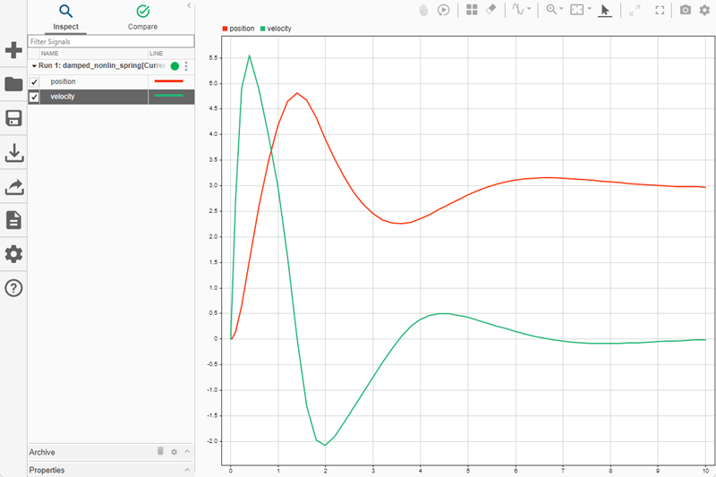
Initially, the spring is compressed. When released, the spring oscillates. Eventually, because the system is damped, the spring comes to rest at its resting spring length of 3 m.

The position and velocity signals plotted in the Simulation Data Inspector.

For more information about viewing logged signal data in the Simulation Data Inspector, see Inspect Simulation Data and Create Plots Using the Simulation Data Inspector.

Access Signal Logging Data Programmatically

You can also analyze the logged workspace data using MATLAB®. By default, all logged simulation data is returned as a single Simulink.SimulationOutput object in a variable named out.

out
out = 

  Simulink.SimulationOutput:

                logsout: [1x1 Simulink.SimulationData.Dataset] 
                   tout: [59x1 double] 

     SimulationMetadata: [1x1 Simulink.SimulationMetadata] 
           ErrorMessage: [0x0 char] 

Signal logging data is grouped in a Simulink.SimulationData.Dataset object with the default name of logsout. When simulation results are returned as a single Simulink.SimulationOutput object, you can access the signal logging data using a dot.

out.logsout
ans = 

Simulink.SimulationData.Dataset 'logsout' with 2 elements

                         Name      BlockPath                        
                         ________  ________________________________ 
    1  [1x1 Signal]      velocity  damped_nonlin_spring/Integrator 
    2  [1x1 Signal]      position  damped_nonlin_spring/Integrator1

  - Use braces { } to access, modify, or add elements using index.

When you log data to the workspace and return a single simulation output, the Simulink.SimulationOutput object contains a property for each logging type. For example, when you log data using signal logging and use the default workspace variable name for the Dataset object, the Simulink.SimulationOutput object has the property logsout that contains the logged signal data. You can use the Configuration Parameters dialog box to enable or disable the Single simulation output parameter. For an example, see Access Data in Simulink.SimulationOutput Object.

Each signal logged using signal logging is stored as an element within the Dataset object. To change the workspace variable name of the signal logging Dataset object, you can use the text box next to the Signal logging parameter in the Configuration Parameters dialog box.

See Also

Model Settings

Objects

Tools

Related Topics