Use Design Evolution Manager with the Fixed-Point Tool
Note
The Design Evolution Manager is available on MATLAB® Online™ only and requires a Simulink® license. This example also requires a Fixed-Point Designer™ license.
Use Design Evolution Manager with Fixed-Point Tool
This example shows how to use the Design Evolution Manager to manage different design versions while using the Fixed-Point Tool and the Lookup Table Optimizer to convert a floating-point model to use fixed-point data types. While this example demonstrates the fixed-point conversion use case, you can use the Design Evolution Manager to organize and analyze any work in which you create different versions of files in your design.
In this example, the Fixed-Point Tool creates many versions of a design, including:
The original floating-point model
The model prepared for fixed-point conversion
Various fixed-point versions of the model
Managing, analyzing, and moving between these different versions of a design can be challenging. The Design Evolution Manager helps you to organize different versions of the same design, understand the relationships between different versions, compare different versions, and store and review notes and data about the versions.
This example shows how to:
Convert your model files into a project.
Create an evolution tree to visually organize the different versions of your design that you store in evolutions.
Create a baseline evolution to store a snapshot of the initial state of the files in the project.
Convert the model to use fixed-point data types. Create evolutions to store snapshots of the design and notes you take at key points in the design process.
Compare evolutions and review your notes to understand changes that were made to the model, then choose which version of the design best meets your requirements.
Generate a report that summarizes the evolution tree.
Set Up Example Files
To use the Design Evolution Manager, all of your design files must be contained in a single project.
Create and open a working copy of the project example files. The MATLAB® software copies the files to an example folder so that you can edit them.
setupDEMExample
The setupExample helper function creates and opens a project called DEM_FPT_Example, which contains a controller_subsystem model to convert to fixed point and a controller_harness model for testing.
Create New Evolution Tree
An evolution tree is a visual representation of a collection of related but different versions of your files, stored as evolutions. Create a new evolution tree to keep track of different design versions created during conversion to fixed point.
1. On the Project tab, in the Tools section, click the button arrow, then click the Design Evolution Manager icon ![]() .
.
2. In the Create New Evolution Tree dialog box, under Evolution Tree Name, enter Convert Controller to Fixed Point. You can enter optional notes under Evolution Tree Notes.
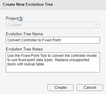
3. Click Create to continue.
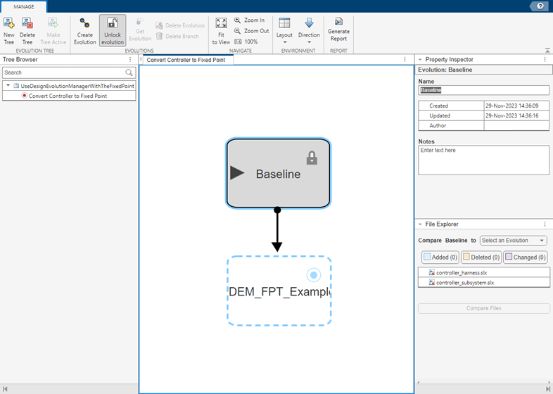
The Design Evolution Manager creates a new evolution tree. The Tree Browser pane shows the Convert Controller to Fixed Point evolution tree in the current project. The record icon shows that this evolution tree is active.
The evolution tree contains the Baseline evolution, which is a copy of all files in the project in their current state. The current files indicator shows that the Baseline evolution is the version of files that are currently open in the project. The Baseline evolution is locked by default to prevent changes you make to project files from being recorded to this evolution. When you start making changes to project files, the Design Evolution Manager automatically creates a new child evolution under the Baseline evolution to record your changes as you work.
Prepare for Fixed-Point Conversion
The first step in the fixed-point conversion process is to use the Fixed-Point Tool to prepare the controller_subsystem model for conversion to fixed point. The preparation step creates a new version of the model files that you may want to reference and return to later.
1. From the project, open the controller_harness model.
2. Open the Fixed-Point Tool. On the Simulink® Apps tab, under Code Generation, click the Fixed-Point Tool icon.
3. In the tool, select New > Optimized Fixed-Point Conversion.
4. Under System Under Design (SUD), select controller_subsystem as the system to convert to fixed point.
5. In the toolstrip, click Prepare.
6. When the preparation checks are complete, save the changes to the controller_subsystem and controller_harness models.
Create Evolution
Use the Design Evolution Manager to check the state of your design and save the prepared model in a new evolution.
The shape of the evolution tree has changed. Because the Baseline evolution is locked, the Design Evolution Manager automatically created the Untitled evolution as a child of the Baseline evolution to record the changes made to project files in the previous step.
1. In the Property Inspector pane, name the new evolution Prepared.
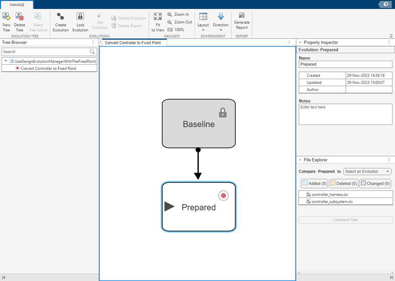
2. On the evolution tree, select the connector between the Baseline evolution and the Prepared evolution. In the Property Inspector pane, the File Explorer shows that the controller_subsystem.slx and controller_harness.slx model files have changed.
3. In the Notes field for the connector, add a note that these file changes are the result of running the preparation step in the Fixed-Point Tool.

Inspect Changes Between Evolutions
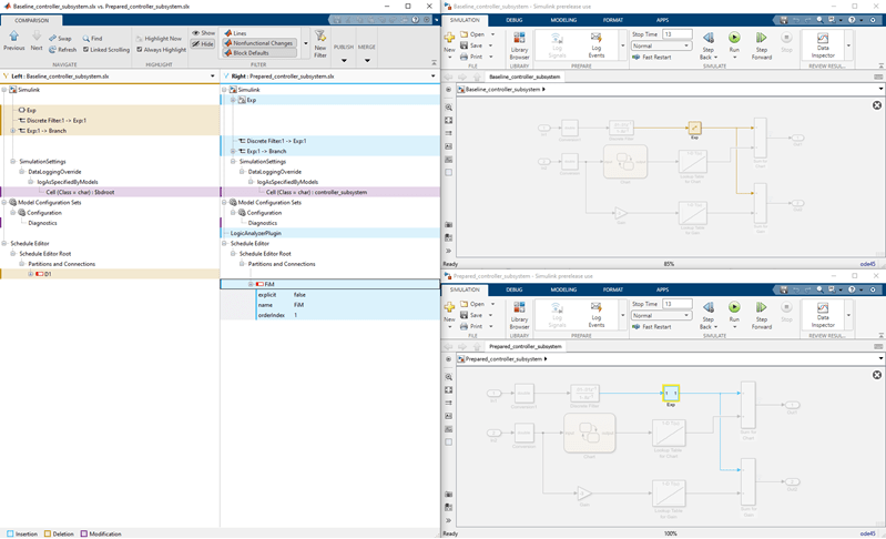
Use the Comparison Tool to compare the version of the files stored in the Baseline evolution to the version of the files stored in the Prepared evolution.
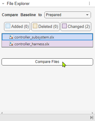
1. Select the connector between the Baseline and Prepared evolutions.
2. On the Property Inspector pane, in the File Explorer section, select the controller_subsystem.slx file. Click Compare Files.
The Comparison tool launches. The version of the model stored in the Baseline evolution is shown in orange, and the version of the model stored in the Prepared evolution is shown in blue. The comparison shows that the Exp block, which is not supported for fixed-point conversion, was automatically isolated during the prepare step in the Fixed-Point Tool.
3. In the Design Evolution Manager, select the Prepared evolution. In the Property Inspector pane, add a note indicating that the Exp block has been isolated and needs to be replaced later.
4. Now that the system is prepared for fixed-point conversion and the changes have been verified, lock the evolution to prevent any further changes from being recorded to the Prepared evolution. In the tree, select the Prepared evolution, then click Lock Evolution in the toolstrip.
Convert to Fixed-Point and Store in Evolution
Use the Fixed-Point Tool to convert the controller model to fixed point. Use the Design Evolution Manager to track your work.
1. In the Fixed-Point Tool, from the Workflow Browser pane, select the Setup window.
2. Under Signal Tolerances, set Relative Tolerance for the Sum:1 and Sum1:1 signals to 0.15.
3. Click Optimize Data Types.
The Fixed-Point Tool determines optimized fixed-point data types for the controller_subsystem based on the specified tolerances. The best solution found has a cost of 416. This solution is automatically applied to the controller_subsystem model.
4. To open the Simulation Data Inspector, click Compare. Visually confirm that the solution meets the specified tolerances for the logged signals.
5. Save the changes to the model.
6. In the Design Evolution Manager, these changes were automatically recorded to the new Untitled evolution, which is a child of the Prepared evolution.
7. Name the new evolution Converted 15%.
8. Add a note to the evolution that the total cost of this design is 416.
Add Conversion Script to the Evolution
In addition to storing the fixed-point version of the model in an evolution, you can also add a copy of the script used to convert the model to fixed point to the Converted 15% evolution you just created.
1. Export the fixed-point conversion script. In the Fixed-Point Tool, click Export Script.
The Fixed-Point Tool exports fxpOptimizationScript.m to the base workspace.
2. Add the fixed-point conversion script to the project. In MATLAB, in the Current Project pane, right-click fxpOptimizationScript.m and select Add to Project.
4. Confirm that the file was added to the evolution. Select the connector between the Prepared evolution and the Converted 15% evolution.
In the Property Inspector pane, the File Explorer shows that the fxpOptimizationScript.m file was added and that the controller_harness.slx and controller_subsystem.slx model files were changed between the Prepared and Converted 15% evolutions.

5. Lock the Converted 15% evolution.
Create Branch in Evolution Tree to Explore Different Fixed-Point Types
Next, try the optimized fixed-point conversion workflow with a larger tolerance. Use the version of the files saved in the Prepared evolution to start from the version of the model files already prepared for fixed-point conversion. Then, run the optimization process again and track your work in a new branch in the evolution tree.
1. Return to the floating-point version of the design after it was prepared for fixed-point conversion. In the Design Evolution Manager, select the Prepared evolution. Click Get Evolution.
The dialog box indicates that the fixed point conversion script, which was not present in the Prepared evolution, will be removed from the active project area.
2. Click OK to continue.
The files in the project are now the version of the design files as they previously were after you prepared them with the Fixed-Point Tool. The shape of the evolution tree has changed, showing that the next evolution created will be a child of the Prepared evolution.
3. Use the Fixed-Point Tool to convert the controller_subsystem to fixed point as before. This time, set the Relative Tolerance for both of the logged signals to 0.20.
Because you loaded the version of the model files from the Prepared evolution, you do not need to run the prepare step in the Fixed-Point Tool again.
4. Click Optimize Data Types to run the conversion.
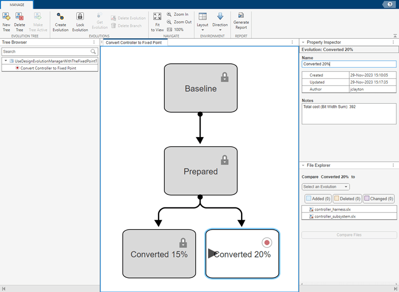
The best solution found has a total cost of 392.
5. Save the changes to the model.
6. Save this version of the design in a new evolution named Converted 20%.
7. Export the fixed-point conversion script and add it to the evolution you just created.
8. Lock the Converted 20% evolution.
9. Add a note to the Converted 20% evolution that the total cost of this version of the design is 392.
Compare Alternate Versions of Design
The final step of fixed-point conversion is to replace the Exp block with a lookup table approximation. The fixed-point versions of the design stored in the Converted 15% and Converted 20% evolutions both produced acceptable results, with the logged signals meeting all specified tolerances. You can review your notes to confirm that the costs of these designs are 392 and 416, respectively. Because the Converted 20% version of the design has a lower cost, choose this branch of the evolution tree to continue your design work.
Replace Unsupported Block with Lookup Table and Save in Evolution
From the Converted 20% version of the design, replace the Exp block with a lookup table approximation.
1. Get the Converted 20% evolution into your active project area and open the controller_harness model.
2. In the model, navigate to the blue exponential subsystem under controller_harness > Model (controller_subsystem) > Exp. Select the Exp block that was isolated in the preparation stage of fixed-point conversion.

3. Open the Lookup Table Optimizer. On the Simulink Apps tab, under Code Generation, click the app icon.
4. In the Lookup Table Optimizer, select Simulink block or subsystem. Click Next.
5. Confirm that the Simulink block path is controller_subsystem/Exp/ReplicaOfSource. Click Collect Current Values from Model, then click Next.
6. Click Optimize, then click Next.
7. Click Replace Original Function.
The Exp block is replaced with a lookup table approximation.

8. Save the changes to the model.
9. In the Design Evolution Manager, a new Untitled evolution was created as a child of the Converted 20% evolution to record the changes made since the Converted 20% evolution was locked. Name this new evolution Exponent Replaced.
10. Select the connector between the Converted 20% evolution and the Exponent Replaced evolution. Add a note that the action taken between these evolutions was to use the Lookup Table Optimizer to replace the Exp block with an optimized lookup table approximation.

Review Design Process and Generate Report
The Design Evolution Manager shows the complete design process used in this example. Design decisions are represented visually by the evolution tree. You can select individual evolutions or connectors to review changes made during the design process and any notes you recorded.
To generate a pdf report that summarizes the evolution tree, click Generate Report ![]() . Enter a title for the report and a name for the pdf file to be generated, then click Generate.
. Enter a title for the report and a name for the pdf file to be generated, then click Generate.
Generate Report
Close Project
Close the project. On the Project tab, in the Close section, click Close Project.
proj = currentProject;
close(proj);
See Also
Apps
- Lookup Table Optimizer (Fixed-Point Designer)
Tools
- Fixed-Point Tool (Fixed-Point Designer)
Related Topics
- About Design Evolutions
- Convert Floating-Point Model to Fixed Point (Fixed-Point Designer)
- Optimize the Fixed-Point Data Types of a System Using the Fixed-Point Tool (Fixed-Point Designer)
- Optimize Lookup Tables for Memory-Efficiency (Fixed-Point Designer)
You can also select a web site from the following list:
Americas
- América Latina (Español)
- Canada (English)
- United States (English)
Europe
- Belgium (English)
- Denmark (English)
- Deutschland (Deutsch)
- España (Español)
- Finland (English)
- France (Français)
- Ireland (English)
- Italia (Italiano)
- Luxembourg (English)
- Netherlands (English)
- Norway (English)
- Österreich (Deutsch)
- Portugal (English)
- Sweden (English)
- Switzerland
- United Kingdom (English)