Configure Model to Export as FMU with Internal Variables
This topic shows how to configure a Simulink® model to export it as a Functional Mockup Unit (FMU) with internal variables. Create internal variables to observe signals that are not exposed by the input and output ports of the FMU. Doing so enables you to access internal signal values and debug your imported FMU during simulation. For more information, see Observe Internal Variables of an FMU (Simulink Test).
In a Simulink model, you can configure logged signals, test points, and datastores as internal variables of the FMU.
This workflow requires the FMU Builder for Simulink support package.
Open Model to Export as FMU with Internal Variables
This example opens a model that is to be exported as an FMU with internal variables. The model consists of a cascaded PID and a mass-spring-damper system. The reference signal specifies the desired position of the mass. The PID controller provides the force as input to the mass-spring-damper system to control the position of the mass.

Configure Logged Signals, Test Points, and Datastores as Internal Variables
The model contains internal signals
controlInputBusSignal,measuredOutput, andcontrolSignalthat are not directly connected to the input or output ports. The value of the signalcontrolSignalis registered in datastorecontrolSignalStore.To mark the signal
controlInputBusSignalfor logging, select the signal, and on the Simulation tab, click Log Signals. For more information on signal logging, see Save Signal Data Using Signal Logging.To configure signal
measuredOutputas a test point, select the signal, and on the Signal tab, click Test Point. For more information on test points, see Configure Signals as Test Points.Create a
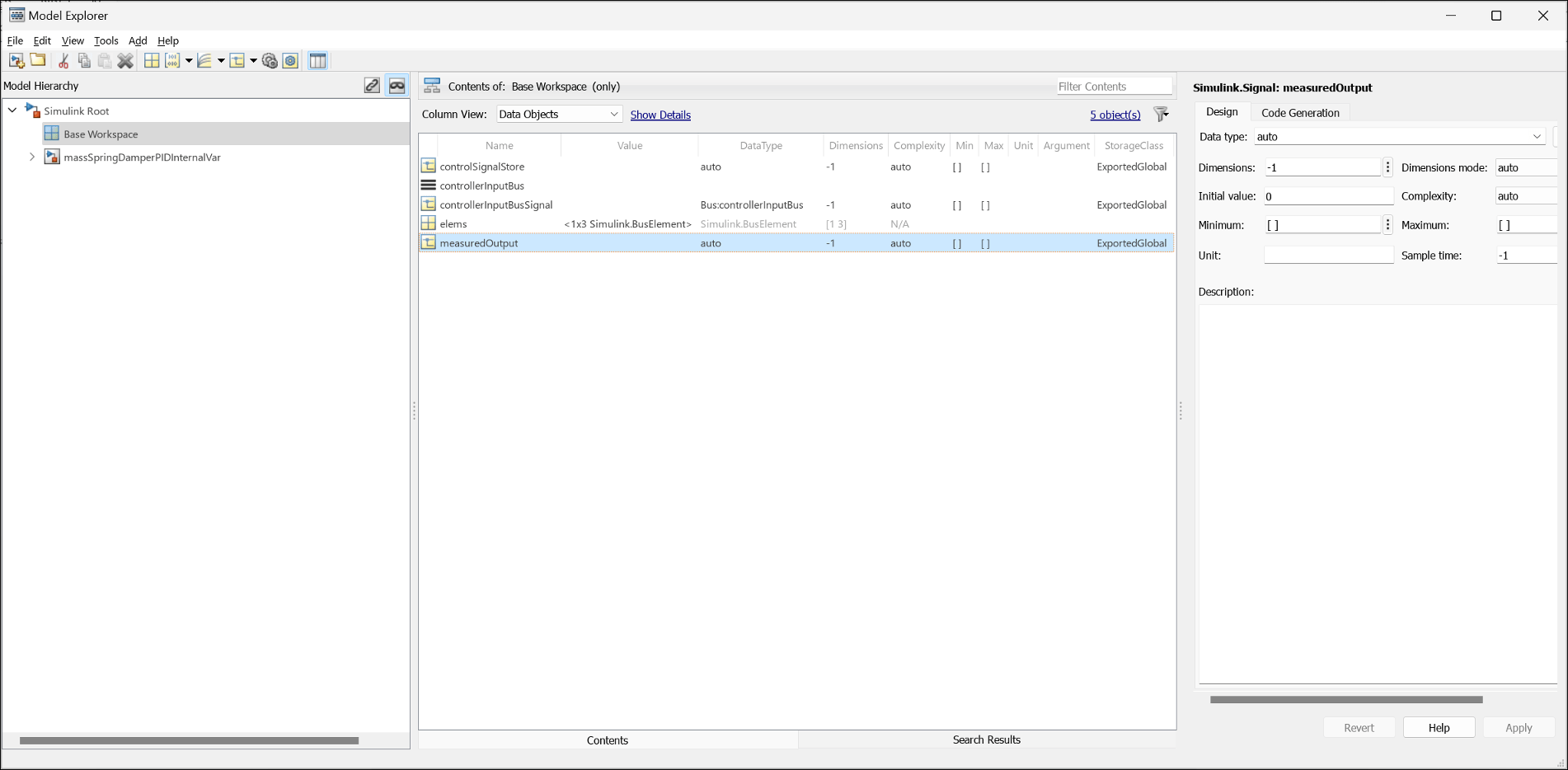
Simulink.Signalobject in the base workspace for each of the signals that you want to export as an internal variable. You can create this object using the command line or the Model Explorer. For more information on creating the object, see the creation section ofSimulink.Signal. The name of the object must match the name of the signal in the model. For example, in this model, the signalmeasuredOutputrequires that you create the followingSimulink.Signalobject:measuredOutput = Simulink.Signal;
In the Design tab of Model Explorer, set the
Data typeandInitial valuefor the object. In the Code Generation tab, set theStorage Classparameter asExported Global.
Alternatively, modify the fields of the
Simulink.Signalobject at the command line. For example, for themeasuredOutputsignal, set the following.measuredOutput.DataType = 'double'; measuredOutput.CoderInfo.StorageClass = 'ExportedGlobal'; measuredOutput.InitialValue = '0';
You must resolve the signals before exporting the model as an FMU. In the Modeling tab on the Simulink toolstrip, select Model Data Editor. Select the logged signals, test points, and datastores to resolve by selecting the corresponding Resolve check box. Update the model to ensure there are no conflicts.
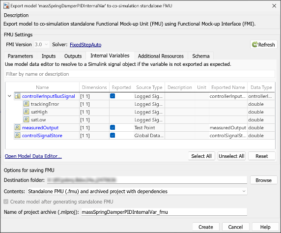
On the Simulation tab, click the drop-down button for Save. In the Export Model To section, click Standalone FMU.... Doing so opens the FMU export dialog box.
Click the Refresh button to compile the model. The Internal Variables tab will lists the signals that can be exported as internal variables. For each signal that you want to export as an internal variable, select the corresponding check box in the Exported column.
Note
Ensure that the model is configured with a fixed-step solver. Variable-step models do not support export as an FMU with internal variables.

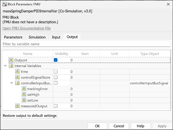
Click Create. Doing so generates the FMU with internal variables according to your specifications. You can view the internal variables of the FMU in the Output tab in the FMU block dialog box.

Limitations
Models with a variable-step solver are not supported for export to FMU with internal variables.
Signals directly connected to the Inport blocks cannot be exported as internal variables.
See Also
Observe Internal Variables of an FMU (Simulink Test)