Code Coverage Report
If you simulate your model in software-in-the-loop (SIL) or processor-in-the-loop (PIL)
mode using the Run button in the SIL/PIL Manager
app, Simulink®
Coverage™ creates a code coverage report for the code generated from the specified model
named
. There are other
ways to create code coverage reports, such as collecting model coverage for a model that
contains custom C/C++ blocks such as S-Functions or C Caller blocks. For more information
about types of reports, see Types of Coverage Reports.model_name
_cov.html
For a model run in SIL/PIL mode, the code coverage report is also opened automatically in the Coverage Details pane.
To access the sldemo_fuelsys
model, in the MATLAB® command window,
execute:
openExample("sldemo_fuelsys");
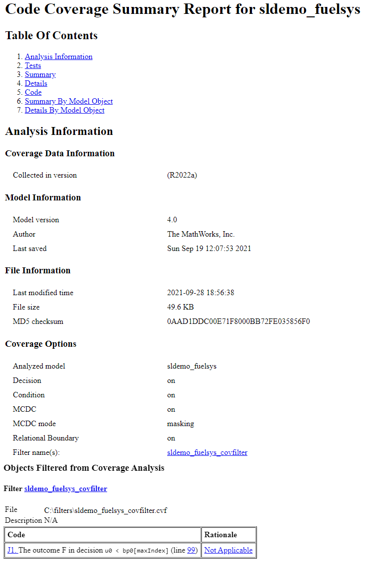
Analysis Information
The analysis information section contains basic information about the model or file analyzed:
Coverage Data Information — displays the MATLAB release version used to collect the coverage data.
Model Information — displays some model metadata such as the version number, author, and date and time it was last saved.
Harness Information — appears if you collect coverage from a Simulink Test™ harness. It provides some information about the harness used.
File Information — displays some data about the file(s) generated during code generation.
Coverage Options — displays the configuration parameters selection values at the time when coverage was analyzed. If a filter is applied, the filter name also appears here.
Objects Filtered from Coverage Analysis — shows the name and full path of the coverage filter file, all the expressions or coverage objective outcomes that were filtered from coverage analysis, and the rationale specified for filtering them.
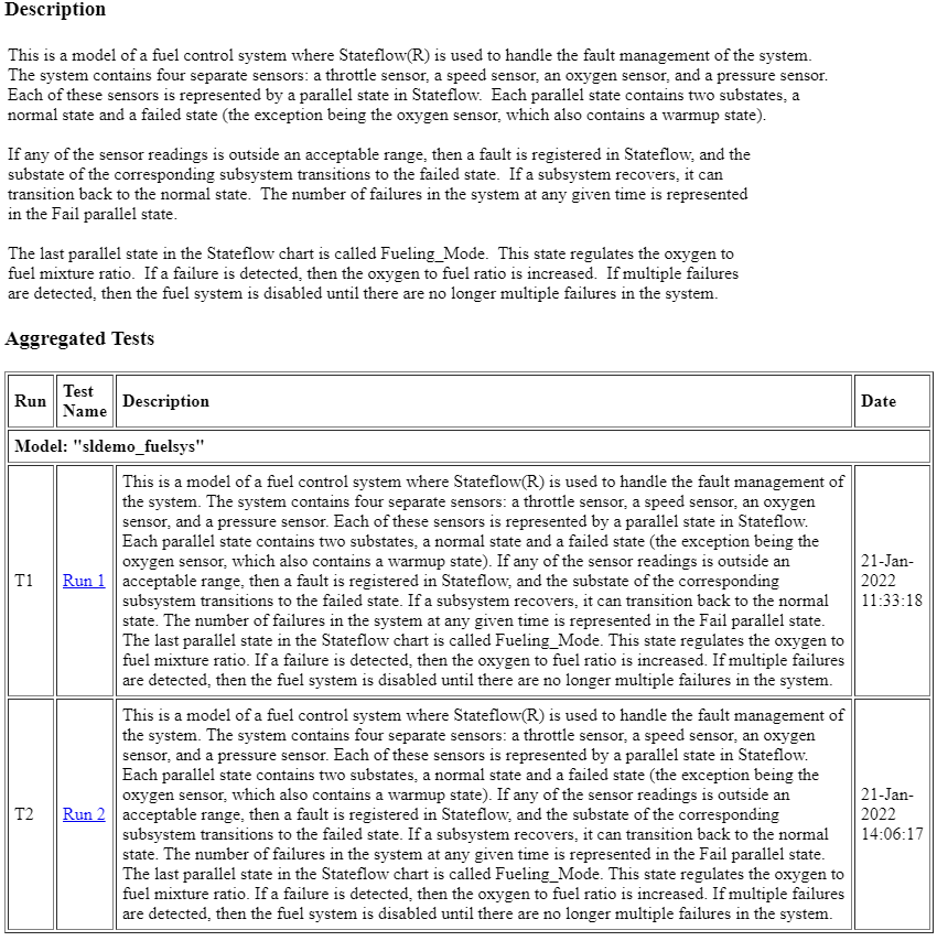
Aggregated Tests
The aggregated tests section appears if you:
Record aggregated coverage results for at least two test cases through the Simulink Test Manager and produce a coverage report for the aggregated results, or
Produce a coverage report for cumulative coverage results in the Coverage Results Explorer.
If you run test cases through the Simulink Test Manager, the aggregated tests section links to the associated test cases in the Simulink Test Manager.
If you aggregate test case results through the Results Explorer, the aggregated tests
section links to the corresponding cvdata
node in the Results
Explorer.
For each run in the aggregated tests section, there is a link to the corresponding results in the Simulink Test Manager or the Coverage Results Explorer.
Aggregated Unit Tests
If you record coverage for one or more subsystem harnesses, the Aggregated Tests section lists each unit test run.
Each unit under test receives an ordinal number n, and each
test for a unit under test receives an ordinal number m in the
style U
n.m.
Summary
The coverage summary has two subsections:
Tests
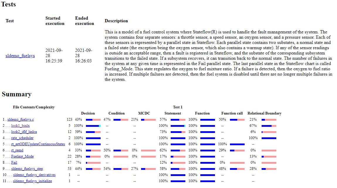
The Tests section contains the simulation start and stop time
of each test case and any setup commands that
preceded the simulation. The heading for each test case includes
any test case label specified using the
cvtest
command. This section only shows when the report does
not contain an Aggregated Tests
section.
Summary
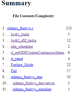
The Summary section contains summaries of the code coverage results reported by file and function. To see detailed results for a specific file or function, in the summary subsection, click the file or function name.
Each file and function has a row in the summary table. The
first column of the summary table represents the cyclomatic
complexity of that file or function. For example, the file
sldemo_fuelsys.c
has a cyclomatic
complexity of 123
. Then, each following
column is labeled with the coverage metric to which it applies.
Each column displays the coverage results for a metric in
percentage of coverage objective outcomes which are satisfied.
The blue section of the bar indicates satisfied objective
outcomes, and the pink part of the bar indicates missing
coverage. Justified objective outcomes are indicated by a light
blue or cyan section of the bar. You can see a justified
objective in the example image on line 2...
look1_binlx
.
Details
The Details section reports the detailed code coverage results. Each subsection of the Details section displays a results summary for a file or function in the analyzed code.
You can access a model object Details By Model Object subsection by left-clicking on the model object.
File Details
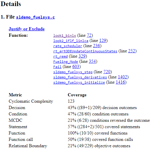
The File Details section contains a results summary for the code file as a whole, followed by a list of functions. Click the function name to go to its applicable subsection of Details.
For example, if you run the model sldemo_fuelsys
in SIL mode,
the generated code is located in sldemo_fuelsys.c
.
The coverage percentages in the File subsection is the total coverage of each of the functions contained within the file. You can click on a function name to view its specific coverage details.
Function Details
Each function details section contains a summary of the test coverage results for the function, a list of the expressions it contains, and links to the parent file and the associated model object.
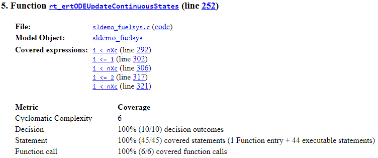
The following graphic shows the coverage results for the
rt_ertODEUpdateeContinuousStates
function for the SIL mode
simulation of the sldemo_fuelsys
example model.
Requirement Testing Details
If you run at least two test cases in Simulink Test that are linked to requirements in Requirements Toolbox™, the aggregated coverage report details the links between model elements, test cases, and linked requirements.
The Requirement Testing Details section includes:
Implemented Requirements — Which requirements are linked to the model element.
Verified by Tests — Which tests verify the requirement.
Associated Runs — Which runs are associated with each verification test.
For an example of how to trace coverage results to requirements in a coverage report, see Trace Coverage Results to Requirements.
Cyclomatic Complexity
You can specify that the model coverage report include cyclomatic complexity numbers in two locations in the report:
The Summary section contains the cyclomatic complexity numbers for each object in the model hierarchy. For a file or function, that number includes the cyclomatic complexity numbers for all their descendants.
The Details sections for each object list the cyclomatic complexity numbers for all individual objects.
Decisions Analyzed
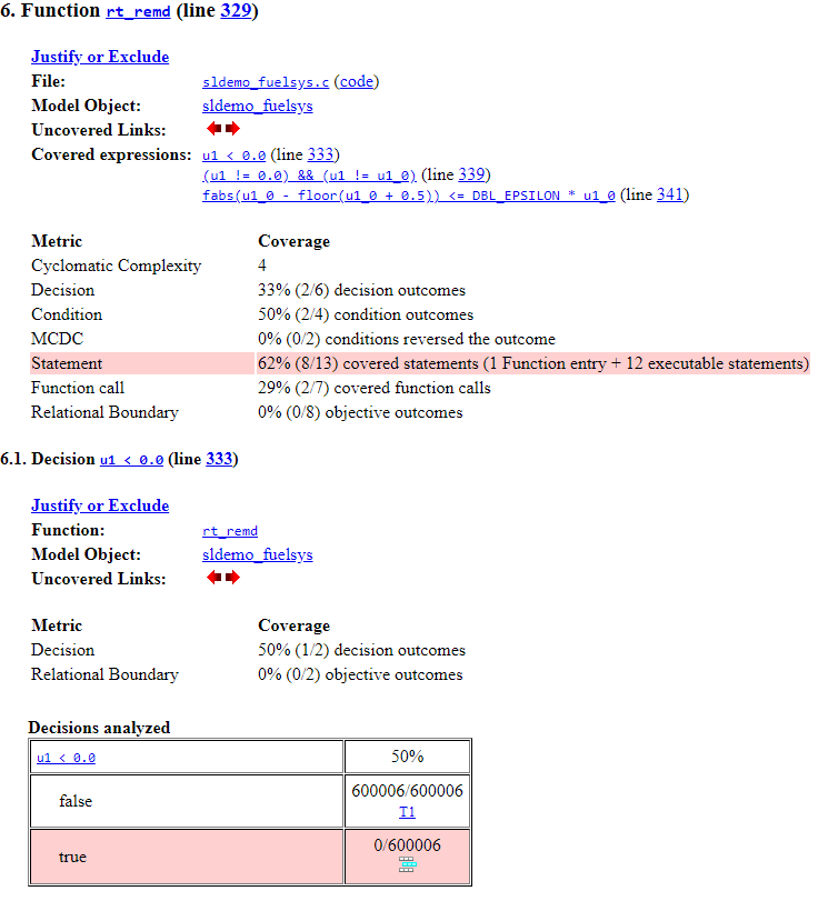
The code coverage report contains a section for each decision within a function. The Decisions analyzed table lists possible outcomes for a decision and the number of times that an outcome occurred in each test simulation. Outcomes that did not occur are in red highlighted table rows. By default, you do not see the Decisions analyzed table for decisions which receive 100% decision coverage. For more information about coverage reporting options, see Accessing Coverage Data from the Results Explorer.
In this example, the decision u1 < 0.0
is
false
for every time step, so the decision receives 50% decision
coverage.
Clicking on the function link rt_remd
scrolls up to the part of the
Details section which displays the function results. Clicking
on the model object link sldemo_fuelsys
opens the model with coverage
highlighting.
Conditions Analyzed
The Conditions analyzed table lists the number of occurrences of true and false condition outcomes for each condition within a function or file.
In this example, the condition that u
is not equal to
0
, u != 0.0
, is true
for
every time step, and the condition that u
is not equal to
u1_0
, u1 != u1_0
is false
for every time step. As a result, each condition receives 50% condition coverage,
resulting in 50% condition coverage for the parent expression.
MCDC Analysis
The MCDC analysis table lists the MCDC condition cases and the extent to which the test cases exercise the conditions that make up each decision. To achieve full MCDC coverage for a decision, the analysis must determine that each condition independently affects the decision outcome.
The MCDC analysis table shows each sub-expression within the parent expression that
Simulink
Coverage analyzes for MCDC coverage. In this example, the parent expression is
(u1 != 0.0) && (u1 != u1_0)
, and the sub-expressions
presented in the MCDC analysis table are u1 != 0.0
, and u1
!= u1_0
.
In the MCDC analysis table, the Decision/Condition column
indicates each deciding input for the decision. The next two columns, True
Out and False Out, indicate the value combinations
that result in the expression returning true
and
false
, respectively, where T
is
true
, F
is false
, and
x
mean the condition outcome does not matter because of logical
short-circuiting.
Note
When you generate C or C++ code from a model, such as by simulating the model in software-in-the-loop (SIL) mode, the generated code uses the short-circuiting logical operators to increase execution speed of the generated code. Disabling logical short-circuiting for model coverage analysis can result in discrepancies between model and code coverage results.
The bold character is the one that needs to independently affect the decision outcome to satisfy that cell of the MCDC analysis table.
Parentheses around the expression indicate that the specified combination of inputs did not occur during the coverage analysis. In other words, the test case did not cover the corresponding condition case.
Some model elements achieve less MCDC coverage depending on the MCDC definition used during analysis. For more information on how the MCDC definition used during analysis affects the coverage results, see Modified Condition and Decision Coverage (MCDC) Definitions in Simulink Coverage.
Cumulative Coverage
After you record successive coverage results, you can Access, Manage, and Aggregate Coverage Results from within the Coverage Results Explorer. By default, the results of each simulation are saved and recorded cumulatively in the report.
If you select Show cumulative progress report in the Settings pane of the Coverage Results Explorer, the results located in the right-most area in all tables of the cumulative coverage report reflect the running total value. The report is organized so that you can easily compare the additional coverage from the most recent run with the coverage from all prior runs in the session.
A cumulative coverage report contains information about:
Current Run — The coverage results of the simulation just completed.
Delta — Percentage of coverage added to the cumulative coverage achieved with the simulation just completed. If the previous simulation's cumulative coverage and the current coverage are nonzero, the delta may be 0 if the new coverage does not add to the cumulative coverage.
Cumulative — The total coverage collected for the model up to, and including, the simulation just completed.
After running three test cases, the Summary report shows how much additional coverage the third test case achieved and the cumulative coverage achieved for the first two test cases.
Decisions Analyzed
The Decisions analyzed table for cumulative coverage contains three columns of data about decision outcomes that represent the current run, the delta since the last run, and the cumulative data, respectively.
For example, in the decision table for u < 0.0
, the decision
is false at every time step in run 1, and remained the same for run 2, so the column
#2 does not add additional coverage for the decision,
resulting in 50% decision coverage for both run 1 and the total.
Conditions Analyzed
The Conditions analyzed table uses column headers #n T and #n F to indicate results for individual test cases. The table uses Total T and Total F for the cumulative results. You can identify the true and false conditions on each input port of the corresponding block for each test case.
For example, the pictured condition table displays a Conditions
analyzed table with cumulative coverage results. The condition
u != 0.0
is true
at every time step during
run 1, with no change in run 2, resulting in 50%
total condition coverage. The condition u1 != u1_0
is
false
at every time step during run 1, with
no change in run 2 resulting in 50% total
condition coverage.
MCDC Analysis
The MCDC analysis #n True Out and #n False Out columns show the condition cases for each test case. The Total Out T and Total Out F column show the cumulative results.
Note
You can calculate cumulative coverage for reusable subsystems and Stateflow® constructs at the command line. For more information, see Obtain Cumulative Coverage for Reusable Subsystems.
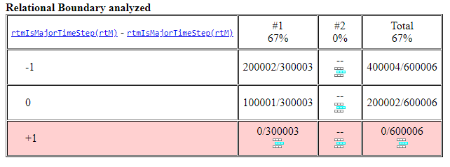
Relational Boundary Analyzed
The Relational Boundary analyzed table for cumulative coverage contains three columns of data about relational boundary outcomes that represent the current run, the delta since the last run, and the cumulative data, respectively.
For example, the relational boundary analyzed for the expression
rtmIsMajorTimeStep(rtM)
shows 67% relational boundary
coverage from run 1 and run 2 does not add additional coverage, resulting in a total
67% relational boundary coverage.
Relational Boundary
If you collect Relational Boundary coverage, Simulink Coverage creates a Relational Boundary table in the code coverage report for expressions that receive relational boundary coverage. The table applies to the explicit or implicit relational operation involved. For more information, see Relational Boundary Coverage.
The tables below show the relational boundary coverage report for the relation
input1 <= input2
. The appearance of the tables depend on the
operand data type.
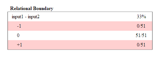
Integers
If both operands are integers (or if one operand is an integer and the other a Boolean), the table appears as follows.
For a relational operation such as
:operand_1
<= operand_2
The first row states the two operands in the form
.operand_1
-operand_2
The second row states the number of times during the simulation that
is equal to -1.operand_1
-operand_2
The third row states the number of times during the simulation that
is equal tooperand_1
.operand_2
The fourth row states the number of times during the simulation that
is equal to 1.operand_1
-operand_2
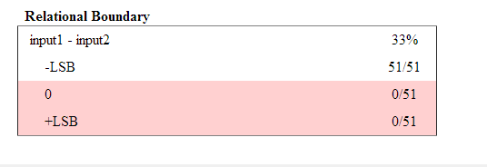
Fixed point
If one of the operands has fixed-point type and the other operand is either a
fixed point or an integer, the table appears as follows. LSB
represents the value of the least significant bit. For more information, see Precision (Fixed-Point Designer). If the two operands have
different precision, the smaller value of precision is used.
For a relational operation such as
:operand_1
<= operand_2
The first row states the two operands in the form
.operand_1
-operand_2
The second row states the number of times during the simulation that
is equal tooperand_1
-operand_2
-LSB
.The third row states the number of times during the simulation that
is equal tooperand_1
.operand_2
The fourth row states the number of times during the simulation that
is equal tooperand_1
-operand_2
LSB
.
Floating point
If one of the operands has floating-point type, the table appears as follows.
tol
represents a value computed using the input values and a
tolerance that you specify. If you do not specify a tolerance, the default values
are used. For more information, see Relational Boundary Coverage.
For a relational operation such as
:operand_1
<= operand_2
The first row states the two operands in the form
.operand_1
-operand_2
The second row states the number of times during the simulation that
has values in the rangeoperand_1
-operand_2
[-tol..0]
.The third row states the number of times during the simulation that
has values in the rangeoperand_1
-operand_2
(0..tol]
during the simulation.
The appearance of this table changes according to the relational operator in the
block. Depending on the relational operator, the value of
equal to 0 is either: operand_1
-
operand_2
Excluded from relational boundary coverage.
Included in the region above the relational boundary.
Included in the region below the relational boundary.
Relational Operator | Report Format | Explanation |
---|---|---|
== | [-tol..0) | 0 is excluded. |
(0..tol] | ||
!= | [-tol..0) | 0 is excluded. |
(0..tol] | ||
<= | [-tol..0] | 0 is included in the region below the relational boundary. |
(0..tol] | ||
< | [-tol..0) | 0 is included in the region above the relational boundary. |
[0..tol] | ||
>= | [-tol..0) | 0 is included in the region above the relational boundary. |
[0..tol] | ||
> | [-tol..0] | 0 is included in the region below the relational boundary. |
(0..tol] |
0 is included below the relational boundary for <=
but above
the relational boundary for <
. This rule is consistent with
decision coverage. For instance:
For the relation
input1 <= input2
, the decision is true ifinput1
is less than or equal toinput2
.<
and=
are grouped together. Therefore, 0 lies in the region below the relational boundary.For the relation
input1 < input2
, the decision is true only ifinput1
is less thaninput2
.>
and=
are grouped together. Therefore, 0 lies in the region above the relational boundary.