Design Optimization to Track Reference Signal (GUI)
This example shows how to optimize controller parameters to track a reference signal using the Response Optimizer. You specify the reference signal without adding any Check blocks to the model.
Model Structure
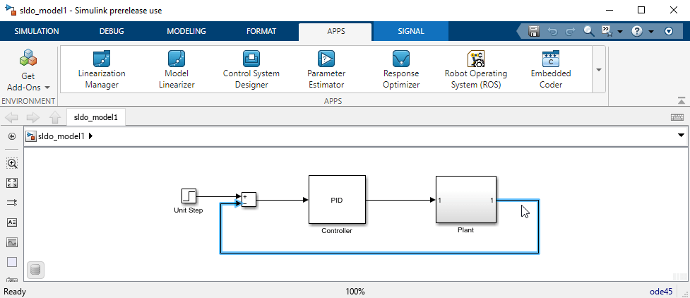
The model sldo_model1 includes these blocks:

Controller block, a PID controller, controls the output of the
Plantsubsystem.Unit Step block applies a step input.
You can also use other types of inputs, such as ramp, to optimize the response generated by such inputs.
Plant subsystem is a second-order system with delay. It contains Transfer Function and Transport Delay blocks.

Design Requirements
The model output must track a reference signal , where t is time.
Specify Reference Signal
Open the Simulink® model.
sys = 'sldo_model1';
openExample(sys);
To learn more about the model, see Model Structure.
To open the Response Optimizer, in the Simulink model window, from the Apps tab, in the gallery, under Control Systems, select Response Optimizer.

Select the model signal to track the reference signal.
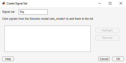
In the New drop-down list, select Signal to open the Create Signal Set window.


To display the signal in the window, click the output of the Plant block in the Simulink model window.

Select the signal to add it to the signal set.

In Signal set, enter
PlantOutputas the selected signal name.
Click OK to create the variable
PlantOutput. It appears in the Data area of the Response Optimizer.Specify the reference signal for the model output to track.
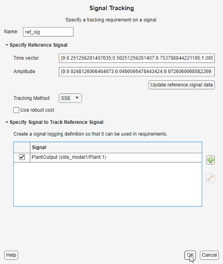
In the New drop-down list, select Signal Tracking to open a Create Requirement window.
In the Name edit box, enter
ref_sig.In the Time vector edit box, enter
linspace(0,50,200)In the Amplitude edit box, enter
1-exp(-0.1*linspace(0,50,200)).
Leave the Tracking Method as
SSEwhich means, at each optimization iteration, the solver attempts to reduce the sum of squared errors between the simulated output and reference signal.Click Update reference signal data.
In the Specify Signal to Track Reference Signal area, select the check-box corresponding to the signal you selected in the previous step, and click OK.

A new reference signal
ref_sigis created and appears in the Data area. The Response Optimization window updates to plot the reference signal.
Specify Design Variables
When you optimize the model response, the software modifies the design variable values to meet the design requirements.
In the Response Optimization tab:
Create a new set of design variables.
In the Design Variables Set drop-down list select New.

The Create Design Variables Set window shows model parameters that you can use as design variables and indicates their locations within the model subsystems.

Add parameters to the design variables set.
Select
Kd,Ki, andKp, and click to add the selected parameters.
The design variables list displays the following parameter settings:
Variable — Parameter name
Value — Current parameter value
Minimum and Maximum — Parameter bounds
Scale — Scaling factor for the parameter
Limit the parameters to positive values. To do so, enter
0for the minimum value of each parameter in the corresponding Minimum field, and press Enter on your keyboard.
Click OK. A new design variable
DesignVarsis created and appears in the Data area of the Response Optimizer.
Optimize Model Response
To view the current model response, click
 Plot Model Response.
The plot shows that the model response does not track the reference signal.
Click
 Optimize.
At each iteration, the optimization solver
Gradient descent(fmincon) modifies the controller parameters to minimize the error between the simulated response and the reference signal. To learn more, see How the Optimization Algorithm Formulates Minimization Problems.The message
Optimization convergedin the Optimization Progress Report indicates that the optimization method found a solution that tracks the reference signal within the tolerances and parameter bounds. For more information about the outputs displayed in the Optimization Progress Report, see Iterative Display.
Verify that the response tracks the reference signal by observing the amplitude versus time plot.

The optimized response closely tracks the reference signal.
To view the optimized parameter values, click
DesignVarsin the Data area of the Response Optimizer. View the updated values in the Variable Preview area.The optimized values of the design variables are automatically updated in the Simulink model.