Enforcing Time and Frequency Requirements on a Single-Loop Controller Design
This example shows how to use Simulink® Design Optimization™ to tune a compensator in a Simulink model. You will add performance requirements to further refine and optimize an initial compensator design performed with Simulink Control Design™ (see Single Loop Feedback/Prefilter Compensator Design (Simulink Control Design)).
Using Simulink Design Optimization software you can graphically specify design and performance requirements for your system by positioning bounds on response plots such as Bode, Nichols, Pole/Zero, Step, or Impulse. Then, using optimization-based methods you can automatically tune compensator elements to satisfy the design requirements. Compensator elements that are tunable via optimization-based tuning include gains, poles, and zeros.
This example requires Simulink Control Design.
Opening the Model
Open the model using the command below, and double click on the orange block to launch the Control System Designer app.
open_system('speedctrl_demo')
Design Overview
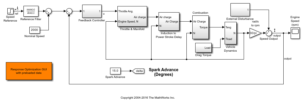
This example designs a single feedback loop for the speed control of an engine. A preliminary PI controller design has been created using Simulink Control Design (see Single Loop Feedback/Prefilter Compensator Design (Simulink Control Design)) and is used as a starting point to further refine the design using response optimization. This example will tune the controller to satisfy the following time-domain and frequency-domain performance specifications:
Requirement 1. A lower amplitude limit on the step response output of -0.1 and a 3 second rise time to reach 95% of the set-point value.
Requirement 2. A maximum overshoot of 1% for the unit step response from Speed Reference to Speed Output.
Requirement 3. A minimum loop gain of 10db over the frequency range 1e-4 to 1 rad/sec to ensure good output disturbance rejection and reference tracking over this frequency range.
Requirement 4. A maximum loop gain of -10db over the frequency range 10 to 1e4 rad/sec to ensure adequate high frequency noise rejection, and together with the low frequency requirement, to ensure a loop bandwidth of between 1 and 10 rad/sec.
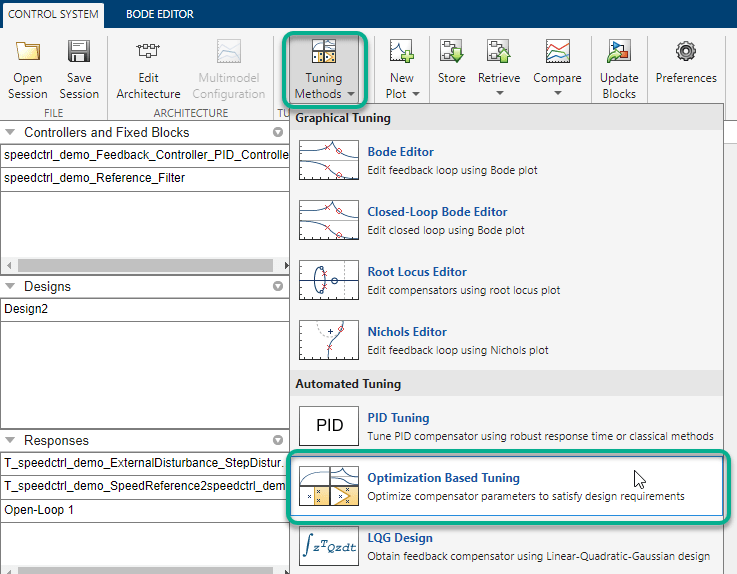
Launching Simulink Design Optimization
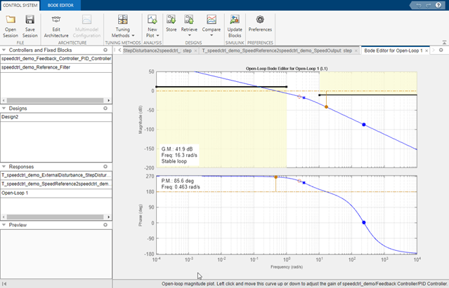
Both time- and frequency-domain response optimization are integrated into the Control System Designer app. In the Control System tab, in the Tuning Methods drop-down list, select Optimization Based Tuning.
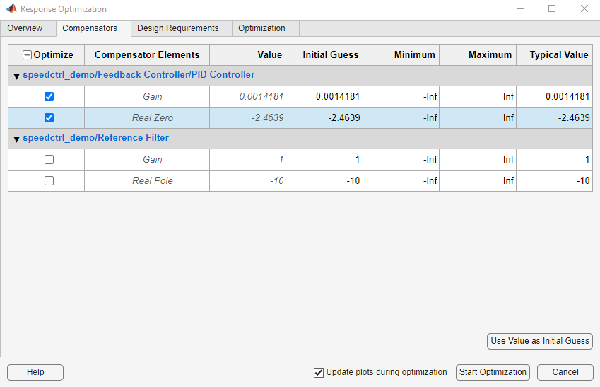
Configuring an Optimization
The first step in configuring an optimization is to select the compensator elements to tune. For this example select the Gain and Real Zero of the PID controller; the reference filter is not tuned.
Adding Design Requirements
The next step is to create the design requirements that the optimization should satisfy. Design requirements are visualized on system response plots. You can add response plots by using the Graphical Tuning or the New Plot drop down lists in the Control System Designer app. The Getting Started with the Control System Designer (Control System Toolbox) example shows how to use the Control System Designer.
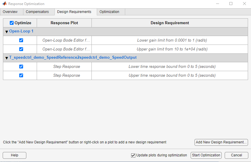
There are two ways to add requirements; you can add them using the Add new design requirement button on the Design Requirements tab in the Response Optimization window or by right clicking on a response plot and selecting Design Requirements->New.
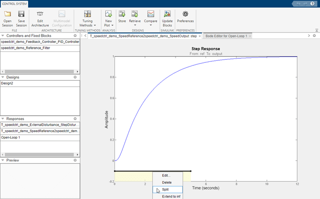
To add Requirement 1 to limit the lower amplitude of the output resulting from a step input,
1. Right click on the lower step response plot and select Design Requirements->New.

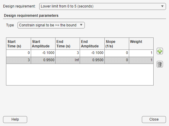
2. Specify the lower limit as -0.1 over the time range 0 to 5 seconds.
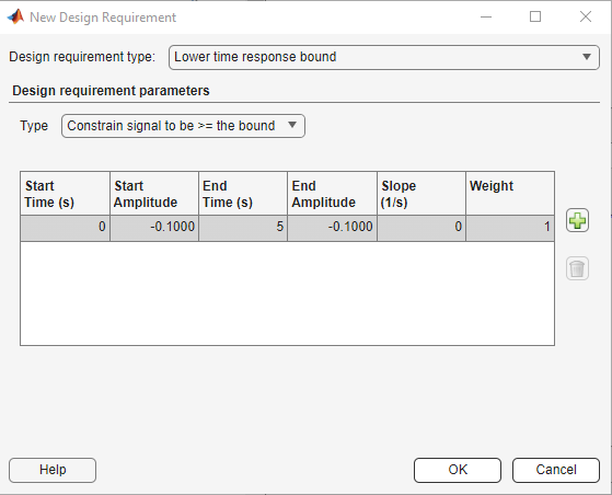
This creates the lower amplitude limit on the step response plot as shown in the next figure.

To add the rise time requirement to the step response, you can graphically manipulate the lower amplitude requirement on the step response plot.
1. Right click the lower amplitude limit requirement and select Split to split a segment into two pieces.
2. Right click the second segment of the requirement and select Extend to inf to extend it to infinity.

3. Right click the second segment of requirement, select Edit, and set the values to represent a 95% rise time at 3 seconds.
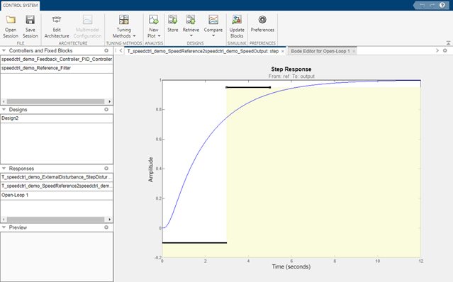
Alternatively you can left click the second segment of the requirement and drag it into position.
Next add Requirement 2 for maximum overshoot to the step response plot. The time-domain constraints on the step response plot are shown in the next figure.
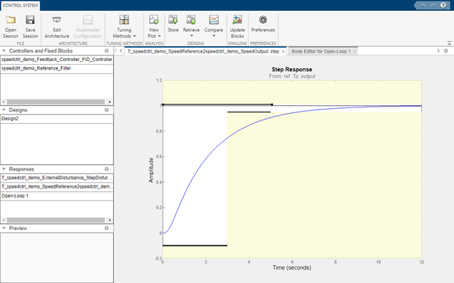
The plot shows the lower amplitude limit of -0.1, maximum overshoot and 95% of the unit step response value of 1.01 and 0.95 respectively.
To add Requirement 3 for minimum loop gain,
1. Click Add New Design Requirement in the Design Requirements tab of the Response Optimization window.
2. Specify the Bode magnitude lower limit for the open loop as 10db over the frequency range 1e-4 to 1 rad/sec.

This creates the minimum loop gain constraint on the Bode magnitude plot as shown in the next figure.

Add Requirement 4 for the maximum loop gain to the Bode magnitude plot to satisfy the overall design specifications. The Bode magnitude plot shows the minimum and maximum loop gain over the specified frequency range.
Select the design requirements for optimization from the Design Requirements tab. After you have selected the requirements, the Design Requirements table appears as shown next:
Running an Optimization
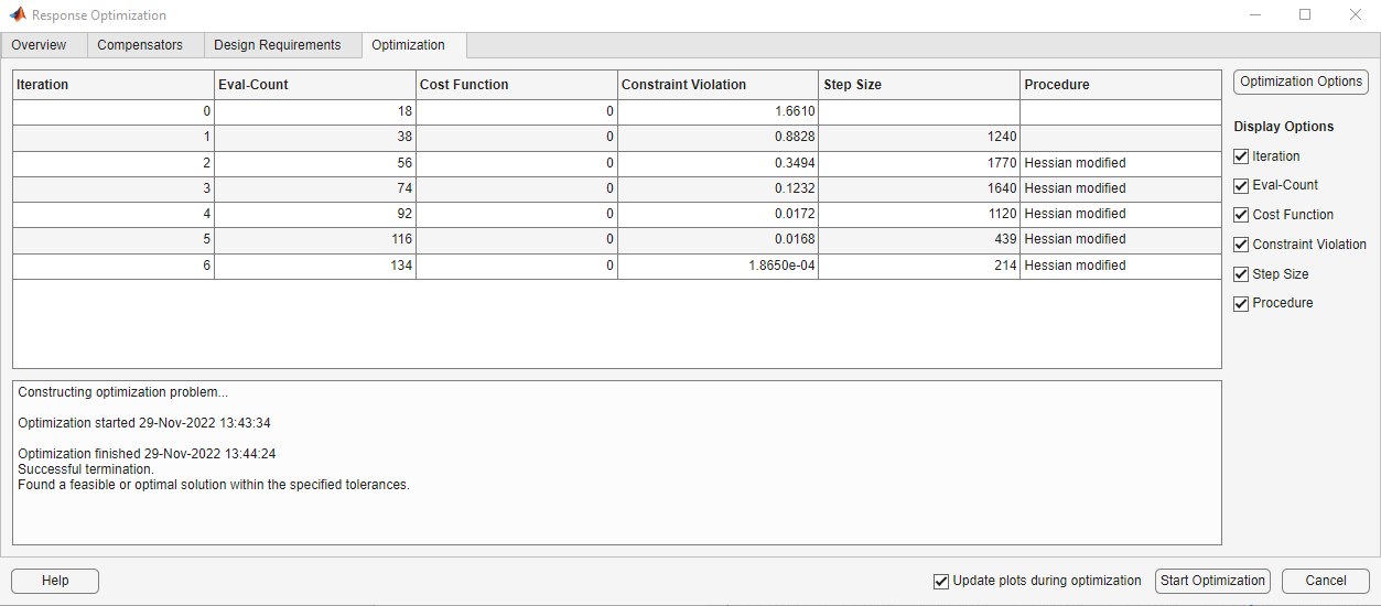
After defining the design requirements and selecting the compensator elements to tune, the optimization is ready to run. Select the Optimization tab and click the Start Optimization button. During optimization the response plots update and numerical progress data is displayed in the Optimization tab.
Inspecting and Verifying the Final Design
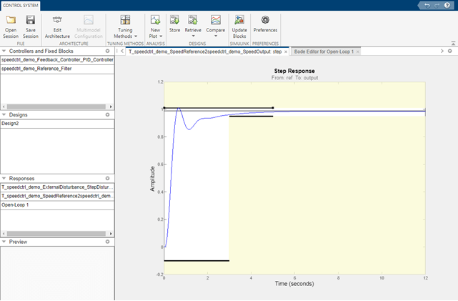
You can check how well the optimized design meets the specified design requirements by viewing the optimized responses (shown below).
To verify the compensator design on the full non-linear Simulink model, return to the Control System Designer and click the Update Simulink Block Parameters button to write the compensator back to the Simulink model. You can now simulate the Simulink model with the newly designed compensator.

bdclose('speedctrl_demo')