Set Run in Kernel Mode (External Mode) Scope Parameters
Connected IO mode and accelerator modes run the simulation algorithm in Simulink® and access the external hardware by using drivers running in operating system kernel mode. The Simulink block diagram is a user interface to your real-time application.
Run in Kernel mode connects your Simulink model to your real-time application. You can use the Simulink block diagram as a user interface as you can in Connected IO mode or accelerator mode.
This procedure uses the model sldrtex_model. To open this model,
in the MATLAB® Command Window, type:
openExample('sldrtex_model')It assumes that you have already loaded that model.
After you have created a real-time application, you can enter scope parameters for signal tracing with Simulink Run in Kernel mode:
In the Simulink Editor, on the Desktop Real-Time tab, click Prepare > Hardware Settings.
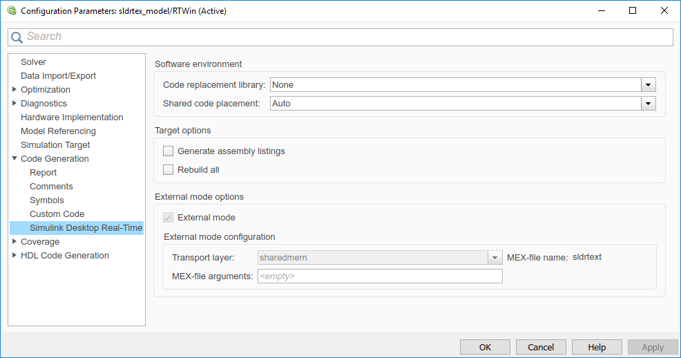
In the Configuration Parameters dialog box, select the Code Generation > Simulink Desktop Real-Time node.
If you select the External mode check box, your changes affect the real-time application.
Check that the MEX-file name label has an entry of
sldrtext. The MEX-filesldrtext.mex*is supplied with the Simulink Desktop Real-Time™ software. This file works with Simulink Run in Kernel mode and supports uploading signal data and downloading parameter values.Click OK.

In the Simulink Editor, on the Desktop Real-Time tab, click Prepare > Control Panel. In the External Mode Control Panel, click the Signal & Triggering button.
Select the Select all check box. From the Source list, select
manual. From the Mode list, selectnormal.The
Xunder Signal selection indicates that a signal is tagged for data collection.Tindicates that the signal is tagged as a trigger signal.In the Duration field, enter the number of sample points in a data buffer. For example, to specify a sample rate of 1000 samples/second and a stop time of 10 seconds, enter:
10000
Select the Arm when connecting to target check box.
If you do not select this check box, data is not displayed in the Scope window.

Click Close.