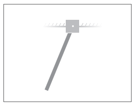
Model a Simple Pendulum
The pendulum is the simplest mechanical system you can model. This system contains two bodies, a link and a fixed pivot, connected by a revolute joint. In this example, you learn how to model and simulate a pendulum using the custom link block you created in the Model a Simple Link. A Revolute Joint block provides the rotational degree of freedom between the link and the pivot fixed at the world frame.

Build Model
At the MATLAB® command prompt, enter
smnew. The Simscape™ Multibody™ model template with commonly used blocks opens up.Delete the Simulink-PS Converter, PS-Simulink Converter, Scope, and Rigid Transform blocks. You do not need them in this example.
Add to the model the Simple Link custom block created in the Model a Simple Link.
Add a Revolute Joint block to the model. You can find this block in the Simscape > Multibody > Joints library. This block provides one rotational degree of freedom between its frames.
Connect the blocks as shown in the image. The port orientation of the Revolute Joint block becomes important when you specify joint state targets, prescribe joint actuation inputs, or sense joint dynamic variables. The Revolute Joint block interprets each quantity as that applied to the follower frame with respect to the base frame, so switching the port connections can affect model assembly and simulation.

In the Brick Solid block dialog box, specify the following parameters. This block connects rigidly to the World frame and therefore has no effect on the dynamics of the multibody model. For more information about multibody dynamics simulations, see Multibody Modeling. You can leave the inertia parameters in their default values.
Parameter Value Units Geometry > Dimensions [4 4 4]cmGraphic > Visual Properties > Color [0.80 0.45 0]N/A
Specify Gravity
The Revolute Joint block uses the common
Z-axis of the base and follower frames as the joint
rotation axis. To ensure the pendulum oscillates under the effect of gravity,
change the gravity vector so it no longer aligns with the
Z-axis. To do this, in the Mechanism Configuration block
dialog box, set Uniform Gravity > Gravity to [0 -9.81 0].
Set Pendulum Starting Position
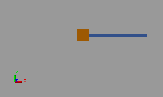
You can specify the desired joint angle using the State Targets menu in the Revolute Joint block dialog box. To do this, select State Targets > Specify Position Target and enter a desired joint angle for the value parameter. For this tutorial, you can leave the angle in its default value, which corresponds to a horizontal pendulum starting position.
Configure Solver
Open the Configuration Parameters. In the Modeling tab, click Model Settings.
In the Solver tab, set the Solver parameter to
ode15s
                                (stiff/NDF)
. This solver is the recommended choice for physical models.Set Max step size to
0.01and click OK. The small step size increases the simulation accuracy and produces a smoother animation in Multibody Explorer. Small step sizes can have a detrimental effect on simulation speed but, in such a simple model, a value of0.01provides a good balance between simulation speed and accuracy.
Assemble Model
Update the block diagram. In the Modeling tab, click Update Model. Multibody Explorer opens with a 3-D view of the model in its initial configuration.
In the Multibody Explorer toolstrip, check that the
View convention parameter is set to Y up
(XY Front). This view convention ensures that gravity is
vertically aligned on your screen. Select a standard view button to refresh the
Multibody Explorer display. The figure shows a front view of
the model. Save the visualization settings by clicking the Save explorer
configuration to model button ![]() .
.

Simulate Model
Run the simulation. Multibody Explorer plays a physics-based animation of the pendulum model.
Save Model
Save the model in a convenient folder under the name
SimplePendulum. You reuse this model in the tutorial
Analyze a Single Pendulum.
See Also
Revolute Joint | Prismatic Joint