Transform Sensor
Sensor that measures the relative spatial relationship between two frames

Libraries:
Simscape /
Multibody /
Frames and Transforms
Description
The Transform Sensor block measures the relative spatial relationship between frames connected to ports F and B of the block. The measured quantities include the relative pose, velocity, and acceleration, which are time-varying physical signals.
You can measure the absolute translational or rotational quantities of a frame by connecting the frame ports F and B of the block to this frame and the world frame of the model, respectively.
The default block units are meter-kilogram-second or MKS (SI). You can use the Simulink-PS Converter or PS-Simulink Converter block to specify the units of an input or output signal, respectively.
Measurement Frame
The measurement frame is:
The frame to use to express the measured quantities.
The location where the observer observes how the measured quantities change over time.
The selection of the measurement frame does not affect the rotational quantities. To see whether a particular quantity is affected, see the Output section.
The Transform Sensor block has five different options for the Measurement Frame parameter. For more information about these options, see the Measurement Frame parameter in the Parameters section.
Rotational and Translational Measurements
The block has four parameterizations to express the measured rotations: angle-axis, quaternion, rotation matrix, and rotation sequence. To enable these parameterizations, in the block dialog box, under Rotation, select corresponding parameters. For example, select the Angle and Axis parameters to use the angle-axis parameterization or select the Quaternion, Transform, or Rotation Sequence parameter to use the quaternion, rotation matrix, or rotation sequence parameterization.
Also, the block has various parameterizations to express rotational velocities and accelerations: x-, y-, and z- coordinates; the time derivatives of a quaternion or rotation sequence; or matrix. To enable these parameterizations, you can select the corresponding parameters under Angular Velocity or Angular Acceleration. For more information, see Rotational Measurements.
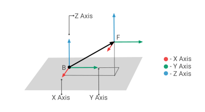
The block has three coordinate systems to express the translational measurements: Cartesian, cylindrical, and spherical. You can select one or more of them at the same time. For more information, see Translational Measurements.
The tables summarize the coordinates of the three systems, and the images show the
diagrams of these coordinate systems. For simplicity purpose, in the images, specify the
Measurement Frame parameter as Base.
Cartesian Coordinates
| Coordinate | Description |
|---|---|
| X | The projection of the vector BF on the
x-axis of the measurement frame. |
| Y | The projection of the vector BF on the
y-axis of the measurement frame. |
| Z | The projection of the vector BF on the
z-axis of the measurement frame. |
Cylindrical Coordinates
| Coordinate | Description |
|---|---|
| Radius | The length of the projection of the vector BF, in the
x-y plane of the measurement frame. |
| Azimuth | The angle of the Radius with respect to the positive
x-axis of the measurement frame. The angle falls in the range
of [-π, π). |
| Z | The projection of the vector BF on the
z-axis of the measurement frame. |

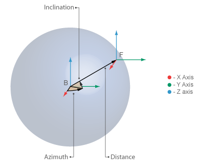
Spherical Coordinates
| Coordinate | Description |
|---|---|
| Distance | The distance between origins of the base and follower frames. |
| Azimuth | The angle of the projection of the vector BF in the
x-y plane with respect to the positive
x-axis. The angle is resolved in the measurement frame and falls
in the range of [-π, π). |
| Inclination | The angle of the vector BF with respect to the
x-y plane of the measurement frame. The angle falls in the
range of [-π/2, π/2]. |
To use a specific coordinate system, select the corresponding parameters. For example, if you want to use the Cartesian system to express the measured relative linear velocity of the follower frame, under Velocity, select the X, Y, and Z parameters.
Examples
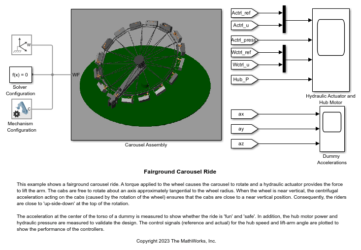
Fairground Carousel Ride
A fairground carousel ride. A torque applied to the wheel causes the carousel to rotate and a hydraulic actuator provides the force to lift the arm. The cabs are free to rotate about an axis approximately tangential to the wheel radius. When the wheel is near vertical, the centrifugal acceleration acting on the cabs (caused by the rotation of the wheel) ensures that the cabs are close to a near vertical position. Consequently, the riders are close to 'up-side-down' at the top of the rotation.
Ports
Frame
Output
Parameters
Extended Capabilities
Version History
Introduced in R2012a