Measure Inertial Properties of Multibody Systems
This example shows how to measure the inertial properties, such as mass and center of mass, of a multibody mechanism or a specific body group. This example uses a model of a centrifugal governor system and measures the inertial properties of the governor by using the Inertia Sensor block. For details on the governor model, open the example.
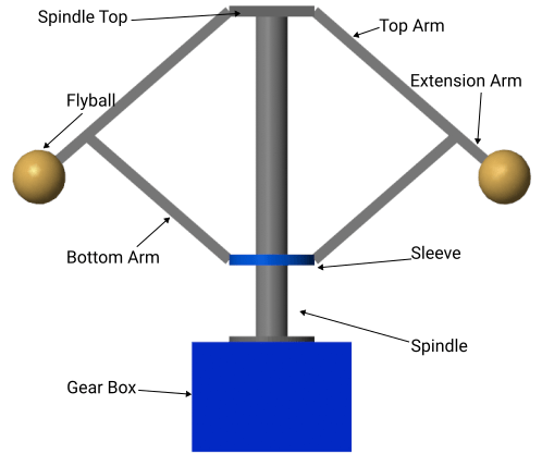
The mechanism of a multibody model encompasses all body elements present in the model. The body element blocks can be any solid, inertia, flexible body, or variable mass block in the Body Elements sublibrary. For example, this diagram shows the body element blocks in the governor.

In a multibody model, a body group is a group of element blocks that are rigidly interconnected. These interconnections can be direct or facilitated by Rigid Transform blocks. The joint blocks separate the mechanism into distinct body groups. For example, this diagram shows the body groups in the governor mechanism and uses the same color to highlight the body elements that belong to the same body group.

To measure the inertia properties of an entire mechanism or a specific body group, use the Inertia Sensor block.
Measure the Mechanism
To measure the inertial properties of a mechanism, you can connect an Inertia Sensor block to any part of the model and specify the sensor extent to measure the whole mechanism. For example, to measure the mass of the entire governor mechanism:
Open the
Governorsubsystem, then add Inertia Sensor, PS-Simulink Converter, and Display blocks.Specify the parameters of these blocks as shown in the table.

Connect the blocks as shown in the image.

Run the simulation. The measured mass agrees with the total mass of the governor mechanism.

In mechanical system analysis, particularly when studying the dynamics of a mechanism, it is common practice to exclude foundation components from measurements. These components, which are typically affixed to a stationary reference point such as the ground, do not significantly influence the dynamics of the system. In a multibody model, these foundation components are called ground bodies. Ground bodies are the body elements that are rigidly connected to the world frame of the model.
In this model, the gearbox is a ground body. To exclude the mass of the gearbox from the measurement, under the Sensor Extent section of the Inertia Sensor block, select Exclude grounded Bodies.

Simulate the model. The measured mass does not include the gearbox.

The Inertia Sensor block never categorizes flexible bodies as ground bodies, even if the flexible bodies rigidly connect to the world frame. To verify this:
Insert a Flexible Cylindrical Beam block to the model.
Update the unit of Radius and Length parameters to
cm.Rename the block to Flexible Body.
Connect the block to the world frame as shown in this diagram.

Simulate the model. The measured mass includes the mass of the flexible body.

Measure a Body Group
You can also measure the inertial properties of a single body group. For example, in the governor model, you can measure the mass of the body group that comprises the right arm and the right flyball.
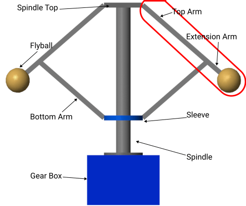
This diagram shows the body element blocks in the body group. Two revolute joints separate this body group from the other body groups in the governor.

To measure the mass of the body group:
Open the Governor subsystem by double-clicking on it.
Verify if an Inertia Sensor, a PS-Simulink Converter, and a Display block are present. If not, add these blocks.
Specify the parameters of these blocks as shown in the table.

Connect the blocks as shown in the image.

Run the simulation. The measurement agrees with the total mass of this body group.
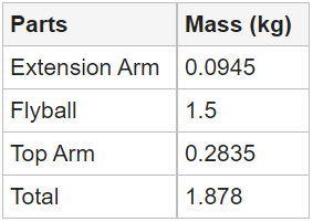
Like other types of joint blocks, the Weld Joint block separates body element blocks into two body groups. For example, add a Weld Joint block between the Extension Arm R and Top Arm R blocks to separate the Top Arm R block from the body group.

Run the simulation. The measured mass does not include the top arm.

In certain applications, you need to use the Weld Joint block to connect body element blocks and measure the connected blocks as a body group. To achieve this goal, you can change the sensor extent of the Inertia Sensor block. For example, to include the Top Arm R block in the measurement, open the Inertia Sensor block and, under the Sensor Extent section, select the Span Weld Joints parameter.

Run the simulation. The measured mass includes the top arm.

Specify the Measurement Frame
The measurement frame of the Inertia Sensor block specifies the frame to use to measure and express the center of mass (COM), inertia matrix, and centered inertia matrix. This section shows how to measure the center of mass (COM) of the highlighted body group and express the measurement in three different frames.

To measure the COM of the highlighted body group:
Open the
Governorsubsystem, then add a Demux block.Specify the parameters of these blocks:

Connect the blocks as shown in this image.

Express Center of Mass in the Attached Frame
You can express the measured COM in a frame that is affixed to this body group. For example, to express the measured COM in the reference frame of the Flyball R block, connect the reference frame to the S port of the Inertia Sensor block and, in the sensor dialog box, specify Measurement Frame as Attached. The specified measurement frame is highlighted in the image with a light blue color.

Simulate the model. The Display block shows the COM at the initial step and the Scope block shows the COM throughout the simulation. Change the legend of the signals as shown in the image. The result shows that the COM is fixed to this measurement frame throughout the simulation.

Express Center of Mass in the World Frame
It is common to express measured quantities in the world frame, which remains stationary during the simulation. To express the measured COM in the world frame, in the Inertia Sensor block dialog box, set Measurement Frame to World. In this image, the world frame is highlighted with a light blue color.

Simulate the model. The Display block shows the COM at the initial step and the Scope block shows the COM throughout the simulation.

The result shows that the x and y coordinates exhibit oscillatory behavior, with the frequency of oscillation between two to six seconds being notably higher compared to other intervals. These results correspond to the right branch of the governor having a more rapid rotation about the z-axis of the world frame during this time frame. These observations are consistent with the simulated behavior of the governor.
Express Center of Mass in a Custom Frame
You can also express the measured quantities in a custom frame. To express the COM in the reference frame of the spindle:
Expose the M port of the Inertia Sensor by setting Measurement Frame to
Custom.Expose the reference frame port of the
Spindleblock by selecting Show Port R under Frames.Reorganize and connect the blocks as shown in the image.

Change the layout of the plots for the Scope block. Double-click the Scope block, select View > Layout, and select 4-by-1 layout.
Connect the 4th input port of the Scope block to the Rotation Inport block.
Run the simulation.
The specified measurement frame is highlighted in the image with a light blue color.

The Display block shows the COM at the initial step and the Scope block shows the COM throughout the simulation.

The plots show that, during the simulation, the y coordinate remains constant while the x and z coordinates are proportional to the angular velocity, which equals the slope of the rotation signal. In other words, the COM is on the xz-plane of the measurement frame, and the frame undergoes rotations about its z-axis. These observations are consistent with the simulation of the governor.