Model a Closed-Loop Kinematic Chain
This example shows how to model a four bar system, which is a closed kinematic chain that
comprise four links through revolute joints. One of the links connects to the
World Frame block and acts as a
ground. Here, use two rigidly connected pivots to replace the link. The custom
DocCompoundRigidBodiesLibrary library provides the body
subsystem blocks used in the example.

Use Revolute Joint blocks to model the joints that connect adjacent links and set the initial states of the joints. You can satisfy a joint state target precisely if the target is kinematically valid and not in conflict with other state targets. Note that in the Z Revolute Primitive (Rz) > State Targets section, you can use the Priority parameter to specify the priority level of a target.
Build Model
To model the four-bar linkage:
Start a new model.
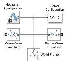
Drag these blocks to the model. The Rigid Transform blocks specify the distance between the two pivot mounts. This distance is the length of the implicit ground link.
Library Block Quantity Simscape > Utilities Solver Configuration 1 Simscape > Multibody > Utilities Mechanism Configuration 1 Simscape > Multibody > Frames and Transforms World Frame 1 Simscape > Multibody > Frames and Transforms Rigid Transform 2 Connect and name the blocks as shown in the figure. Make sure that the base frame ports of the Rigid Transform blocks connect to the World Frame block.

From the Simscape > Multibody > Joints library, drag four Revolute Joint blocks into the model.
At the MATLAB® command prompt, enter
openExample('sm/DocDoublePendulumModelExample','supportingFile','DocCompoundRigidBodiesLibrary.slx'). A custom library with compound body subsystem blocks opens up.From the
DocCompoundRigidBodiesLibrarylibrary, drag the following blocks.Block Quantity Pivot Mount 2 Binary Link A 2 Binary Link B 1 Connect and name the blocks as shown in the figure. Make sure that you position the frame ports of the custom body subsystem blocks exactly as shown.

Specify Block Parameters
In the Rigid Transform block dialog boxes, specify the offset between the pivot mounts and the world frame. The pivot mounts are assumed to be symmetrically positioned about this frame.
Parameter Crank-Base Transform Rocker-Base Transform Translation > Method Standard AxisStandard AxisTranslation > Axis -Y+YTranslation > Offset 15in units ofcm15in units ofcmIn each binary link block dialog box, specify the length parameter.
Block Length (cm) Binary Link A 10Binary Link B 35Binary Link A1 20
Guide Assembly and Visualize Model
Guide model assembly by specifying the desired initial angle for one or more joints in the model. To specify an initial angle of 30° for the Base-Crank joint:
In the Base-Crank Revolute Joint block dialog box, expand State Targets and select Specify Position Target.
Specify the Value parameter as
-30deg.For the Coupler-Rocker Revolute Joint block, in the Z Revolute Primitive (Rz) > State Targets section, select the Specify Position Target parameter, and specify the Value parameter as
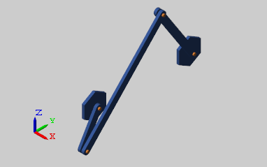
0degand Priority parameter asLow (approximate).On the Modeling tab of the Simulink® Toolstrip, click Update Model. Multibody Explorer opens with a static display of the four-bar linkage in its initial configuration. The image shows the isometric view of the four-bar linkage.

Verify Model Assembly
To check whether and how precisely the state targets were met, you can use the Simscape™ Variable Viewer.
To open the Simscape Variable Viewer, on the Debug tab of the Simulink Toolstrip, in the Diagnostics section, select Simscape > Variable Viewer.
As shown in the image, the yellow marker indicates that the Base-Rocker Revolute Joint state target was satisfied approximately only. The remaining green marker indicates that the Base-Crank Revolute Joint state target was satisfied precisely.

Simulate Model
Run the simulation. Multibody Explorer shows a 3-D animation of the four-bar assembly. The assembly moves due to gravity.
To see a complete model of the four–bar assembly, enter
openExample("sm/DocFourBarLinkageModelExample")at the
MATLAB command prompt.
See Also
PS-Simulink Converter | Revolute Joint