Generate SoC Software Model
R2026bWhen using the IP core generation workflow to target your SoC FPGA, you can generate a software model in addition to the FPGA model. This action generates two models: a host interface model and a software interface model. It also generates two libraries that contain the interface blocks used in the generated models.
The software interface model and its library are generated only if you have Embedded Coder® and SoC Blockset™ Support Package for AMD FPGA and SoC Devices installed.
You can use the host interface model to control the reference design on the board, including your FPGA user logic, from the Simulink® model, without Embedded Coder.
The software interface model enables you to target your software algorithms to the ARM® processor on the board, including:
External mode simulation
Full deployment
Save the generated models and libraries after generation. When you regenerate the library interface blocks, any changes, such as adding an AXI-Lite port, propagate to the saved models the next time you open them. Save the updated library over the previous library model to propagate the changes to existing interface models. If you do not want to update previous models, save the new generated library with a new name.
Software Interface Model Styles
When you generate a software interface model from the IP core generation workflow, the workflow determines the software interface model style based on the interfaces mapped in your design. The generated model enables communication between the processor software and the FPGA logic deployed to the target hardware.
The workflow supports these software interface model styles:
Rate-based software interface model — Uses a rate-based execution model. The workflow generates this model style for designs that use AXI-based interfaces and do not use an interrupt interface.
Task-based software interface model — Uses interrupt-driven execution. The workflow generates this model style for designs that use an interrupt interface.
By default, the workflow generates a rate-based software interface model. If your design maps one or more DUT ports to an interrupt interface, the workflow automatically switches to a task-based software interface model because rate-based software interface model generation does not support interrupt interfaces.
| Interface Mapping | Generated Software Interface Model |
|---|---|
AXI4, AXI4-Lite, AXI4-Stream, AXI4 Master | Rate-based |
Any interrupt interface present | Task-based |
To generate a task-based software interface model, you must have SoC Blockset for AMD and the SoC Blockset Support Package for AMD FPGA and SoC Devices installed. The selected hardware board must also support task-based software interface model generation.
Generate Software Model
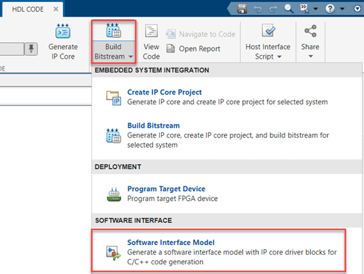
To generate a software model, navigate to the HDL Code tab, and in the Deploy section, expand the Build Bitstream menu. Then, select Software Interface Model.
Host IIO Interface Model and Library
Use the generated host interface model to develop Simulink algorithms that interact with the FPGA data while running on the board. This model enables parallel processing in Simulink and interaction with all or part of your application targeted on the FPGA.
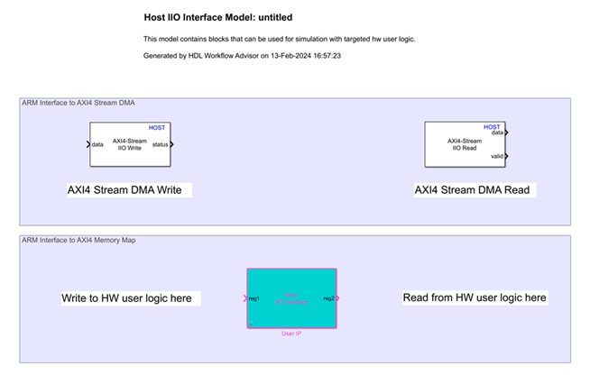
In the top shaded area, ARM Interface to AXI4 Stream DMA, you can stream data to and from the hardware and optionally add algorithms to operate on the data stream. You can modify the parameters on the blocks to control the data format.
In the bottom shaded area, ARM Interface to AXI4 Memory Map, you can optionally add algorithms to write or read the AXI-Lite registers that you specified as ports on your targeted subsystem.
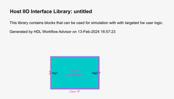
The IP core generation workflow also generates a library that contains a Host IIO Interface block, representing the user IP.
Software Interface Model and Library
Use the generated software interface model to target your software algorithms to the ARM processor on the board. Depending on the mapped interfaces, this model can include AXI4 Stream DMA Read, AXI4 Stream DMA Write, Hardware Interrupt, and Read/Write Register blocks. Use these blocks to implement your software algorithm.
Before implementing your algorithm, remove any unused blocks or sections from the model. Then, deploy code generated from this model to the board to run along with the FPGA user logic.
Use this model to:
Stream FPGA data to and from the ARM processor.
Control the FPGA data path by changing the parameters on the AXI4 Stream DMA Read and AXI4 Stream DMA Write blocks.
Read or write any AXI-Lite ports that you have specified on your FPGA user logic.

The top shaded area, ARM Interface to AXI4 Stream DMA, contains Write Task and Read Task subsystems.
When you generate models for an SoC application, the software model contains these tasks. These tasks import the data stream to the ARM processor, and then they export the processed data back to the FPGA. Each task is triggered by a Hardware Interrupt block.
The bottom shaded areas include FPGA Interrupt with an Interrupt Task subsystem, and ARM Interface to AXI4 Memory Map with a Control Task subsystem. Use the interrupt task to trigger an algorithm from an FPGA interrupt signal. Use the control task to read or write FPGA AXI-Lite registers that you specified as ports on your targeted subsystem. You can generate ARM code from this section of the model and run it in external mode. Alternatively, you can fully deploy the code to the board.
Associate Task with Interrupt
To associate a task with a hardware interrupt, use the Hardware Mapping tool.
Note
The generated software interface model contains Hardware Interrupt blocks only when the design uses one or more interrupt interfaces. If your design does not use interrupt interfaces, the generated model does not require interrupt mapping.
To open the tool, click the Hardware Mapping button on the block mask of the Hardware Interrupt block.
In the Mapping Browser, select the task that you want to associate with the interrupt block.
Select the interrupt group and populate the interrupt name with the name specified in the relevant task. For example, for FPGA Stream Write interrupt:

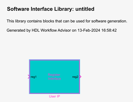
The IP core workflow also generates a software library that contains a Register Interface subsystem, representing the user software IP.
See Also
Hardware Interrupt | Hardware Mapping

