Stream from Processor to FPGA Template
Use the Stream from Processor to FPGA template to create an SoC Blockset™ model for designing a datapath from software (Processor) to hardware (FPGA). To create a project using the Stream from Processor to FPGA template, follow the steps in Create SoC Model Using SoC Blockset Template. Then, add your FPGA algorithm in the FPGA subsystem and your processor algorithm in the Processor subsystem.
Template Structure
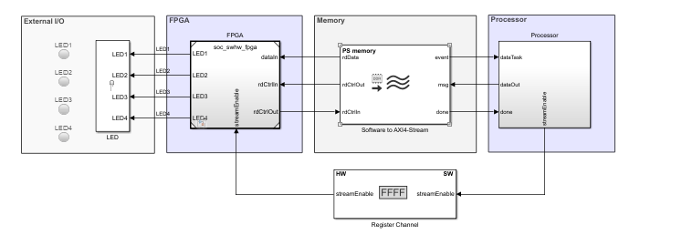
The Stream from Processor to FPGA template comprises three models: the Top model, the FPGA model, and the Processor model. This template models a counter as the test data source and minimal logic for the FPGA and processor algorithms. Use this template as a guide, replacing the FPGA algorithm and processor algorithm with your own functionality.
The processor controls the output ready signal in the FPGA
Algorithm Wrapper subsystem by using the streamEnable port. The
processor passes the data to the FPGA through a Memory Channel
block. The Channel Type parameter in the Memory
Channel block is set to Software to AXI4-Stream via
DMA to model the direct memory access (DMA) data transfer through
shared external memory.
The processor generates test data and performs additional computing. The additional computation is implemented in the template as a pass-through wire. Then, the processor writes the computed data to the memory.
Modify Project
Modify the Processor Model
In the MATLAB® Toolstrip, on the Project Shortcuts tab, click Open Processor model to open the processor model. In the Processor Algorithm Wrapper subsystem, two areas are highlighted blue (which represents user code) as shown in this figure. One highlighted area appears in the Processor Algorithm block, and the other highlighted area appears in the Test Source block.
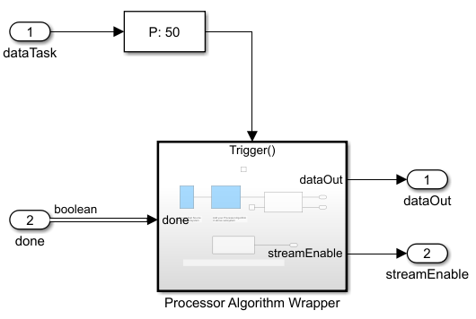
Processor Algorithm block – Replace the internal Processor Algorithm block (highlighted in blue) with your desired algorithm.
Test Source block – This block generates a ramp signal. Modify the test source to your needs or replace it with an alternative source block.
Stream Enable for DUT block – This block contains a control logic to ensure that the memory is primed before continuous streaming begins. In the control logic, the streamEnable signal is asserted high only after available buffers in the memory channel are filled completely.
Modify the FPGA Model
In the MATLAB Toolstrip, on the Project Shortcuts tab, click Open FPGA model to open the FPGA model. In the FPGA Algorithm Wrapper subsystem, the FPGA Algorithm block is highlighted green (which represents user code).
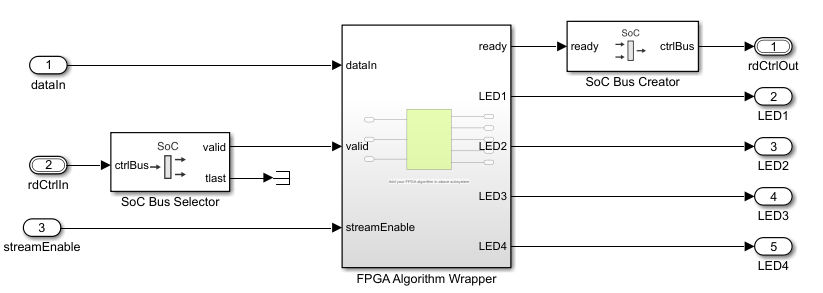
Double-click the FPGA Algorithm Wrapper subsystem to open the model. The FPGA algorithm extracts four bits from the input data to drive the LEDs on the hardware. The status of these LEDs indicates that the processor is writing stream data to the FPGA. Replace this block with your own FPGA algorithm. Add inputs and outputs as required.
Tip
When your FPGA model includes more than one IP, define each IP as a subsystem and connect the subsystems using a Stream Connector or Video Stream Connector block. For additional information, see Considerations for Multiple IPs in FPGA Model.
To enable consistent simulation behavior, on the Project Shortcuts tab, click Open FPGA model tab and repeat this step.
Modify the Register Channel
The top model of the template includes a register channel to communicate between the processor and the FPGA model. Use the register channel to configure the FPGA model or to read and check status registers. The Register Channel block in the template includes one register. To add additional registers, modify the Register Channel block parameters, the FPGA algorithm, and the processor algorithm by following these steps.
Add registers to the register channel – Double-click the Register Channel block to open the block mask and add additional registers as needed. Adding registers creates additional ports on the Register Channel block. For additional information, see the Register Channel block.
Add ports to the Processor model – Navigate to the Processor Algorithm Wrapper subsystem. To navigate to the Processor model, click Open Processor model on the Project Shortcuts tab. Double-click the Processor Algorithm Wrapper subsystem to modify it.
For write registers, add an output port and logic to drive a value to the added output port. For read registers, add an input port and logic to process the information returned from a read register. From the top model, wire the port to the Register Channel block.
Add ports to the FPGA model – Navigate to the FPGA Algorithm Wrapper subsystem. To navigate to the FPGA model, click Open FPGA model on the Project Shortcuts tab. Double-click FPGA Algorithm Wrapper subsystem to modify it.
For write registers, add an input port and logic to process the information returned from a read register. For read registers, add an output port and logic to drive a value to the added output port.
From the top model, wire the new port to the Register Channel block.
See Also
Use Template to Create SoC Model