Memory Channel
Stream data through a memory channel
The Memory Channel block will be removed in a future release. Use one of these blocks instead:
Libraries:
SoC Blockset /
Memory
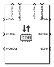
Description
The Memory Channel block streams data through external memory. Conceptually, it models data transfer between one algorithm and another, through shared memory. The algorithm can be hardware logic (HW), a processor model, or I/O devices. The writer algorithm requests access to memory from the Memory Controller block. After access is granted the writer algorithm writes to a memory buffer. In the model, the data storage is modeled as buffers in the channel. When deploying on hardware, the data is routed to an external shared memory.
This block can be configured to support any of these protocols:
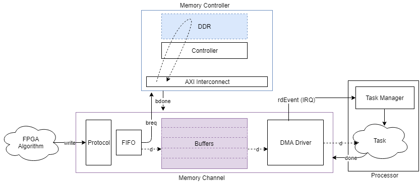
AXI4-Stream to Software via DMA – Model a connection between hardware logic and a software task through external memory. The writer puts data into the channel using a MathWorks® simplified AXI stream protocol and the reader (processor) gets data from a DMA driver interface. The channel models the datapath and software stack of that connection including a FIFO, DMA engine, interconnect and external memory, interrupts, kernel buffer management of the DMA driver, and data transfers to the software task. For more information about MathWorks simplified AXI stream protocol, see AXI4-Stream Interface.
This image is a conceptual view of a Memory Channel block, streaming data from an FPGA algorithm to a processor algorithm.
Software to AXI4-Stream via DMA – Model a connection between hardware logic and a software task through external memory. The writer (processor) streams data into the channel via a DMA driver using a MathWorks simplified AXI stream protocol. The channel models the datapath and software stack of that connection including a FIFO, DMA engine, interconnect and external memory, interrupts, kernel buffer management of the DMA driver, and data transfers from the software task. For more information about the MathWorks simplified AXI stream protocol, see AXI4-Stream Interface.
This image is a conceptual view of a Memory Channel block, streaming data from a processor algorithm to an FPGA algorithm.

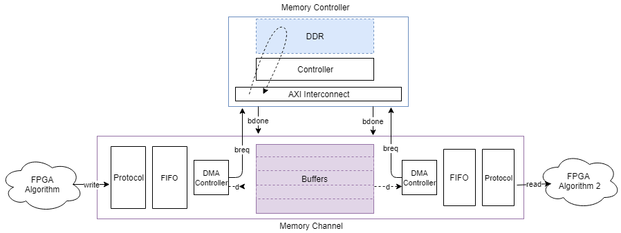
AXI4-Stream FIFO – Model a connection between two FPGA algorithms through external memory. The writer puts data into the channel as a master using the MathWorks simplified AXI stream protocol and the reader receives data from the channel as a slave using the same protocol. The channel behaves as a first in first out (FIFO) memory. The channel models the datapath of the connection. The Memory Channel block includes an intermediate burst-level FIFO, DMA engine, interconnect, and external memory. The external memory itself is managed as a circular buffer, where a buffer must be written before it can be read. For more information about the MathWorks simplified AXI stream protocol, see AXI4-Stream Interface.
This image is a conceptual view of a Memory Channel block, streaming data from one FPGA algorithm to another FPGA algorithm.
AXI4-Stream Video FIFO – Model a connection between two hardware algorithms through external memory. This channel structure is similar to the AXI4 Stream FIFO configuration, but the writer and reader are using the MathWorks streaming pixel protocol, along with a back-pressure signal. For more information, see AXI4-Stream Video Interface.
AXI4-Stream Video Frame Buffer – Model a connection between two hardware algorithms through external memory, using full video frame buffers. The protocol is the MathWorks streaming pixel protocol with back pressure. Also, the reader can ensure that the frame buffer is synchronized with downstream video timings by asserting an FSYNC protocol signal. The datapath includes a Video-DMA (VDMA) engine and the external memory buffers are managed as a circular buffer of full video frames. The channel structure is identical to the structure of AXI4 Stream FIFO channel type.
AXI4-Random Access – Model a connection between two hardware algorithms through external memory, using the MathWorks simplified AXI4-Master protocol. Both the writer and the reader are masters, the channel is a slave in both cases. The external memory is unmanaged (there are no logical buffers, and no circular buffer). It is up to the reader and writer to coordinate timing on accesses to ensure the integrity of the data. For more information, see Simplified AXI4 Master Interface.
This image is a conceptual view of a Memory Channel block, with random-access to the memory for writing, and random-access to the memory for reading.

For more information on the available protocols, see External Memory Channel Protocols.
Limitations
A model containing a Memory Channel blocks does not support simulation stepping. For more information on simulation stepping, see Debug Simulations in the Simulink Editor.
Ports
Input
Output
Parameters
This parameter is read-only.
This parameter shows a link to the currently selected hardware board. Click the link to open the configuration parameters, and adjust the settings, or choose a different board.
To learn more about configuration parameters, see FPGA design (PS mem controllers).
This parameter is read-only.
This parameter shows a link to the implementation information specific to the model. Click the link to view the information (opens in new window).
Select this parameter to enable memory simulation with high accuracy. Clear for faster simulation performance.
Tip
To enable performance logging, set this parameter to
on. Use the Performance Report to display performance metrics.
on— The block simulates memory transactions with burst accuracy. Bursts are constructed and arbitrated for access to memory.off— Memory transactions are purely behavioral, allowing fast simulation.
To see an example that uses this feature go to Accelerate SoC Simulation by Varying Abstraction Levels.
Main
Specify the protocol for the channel. Choose one of the following values:
AXI4-Stream to Software via DMA
Software to AXI4-Stream via DMA
AXI4 Stream FIFO
AXI4 Stream Video FIFO
AXI4 Stream Video Frame
                                            Buffer
AXI4 Random Access
Note
You can use a simplified memory block for the following configurations (recommended):
AXI4-Stream to Software via DMA — Use an AXI4-Stream to Software block.
Software to AXI4-Stream via DMA — Use a Software to AXI4-Stream block.
AXI4 Stream Video Frame Buffer — Use an AXI4 Video Frame Buffer block.
AXI4 Random Access — Use an AXI4 Random Access Memory block.
These blocks provide a preconfigured and simplified view per each channel type.
For additional information about memory channel protocols, see External Memory Channel Protocols.
This parameter is read-only.
The size in bytes of the region. This value is calculated as the number of buffers multiplied by buffer size.
Example: If Buffer size is 1024, and the number of buffers is set to 8, then Region size is 8192.
Specify the size in bytes of each buffer in the region.
The following rules apply when setting burst and buffer sizes.
The Burst Length of a given channel interface, calculated in bytes, must be less than 4096 bytes. To calculate the burst size in bytes, the channel interface scalar datatype is converted to bytes and then multiplied by the Burst Length.
The Burst Length can be set above 256, but will warn if generating to an AXI-based target platform. AXI-based memory systems have a maximum burst length of 256.
The Channel Length must be an integer multiple of burst length or the burst length must be an integer multiple of channel length. That is, it must be possible to either chunk the incoming channel data to a whole number of bursts or to gather a whole number of incoming channel data to a single burst.
The Buffer Size must be a whole number of bursts. This must be true for both the writer’s burst size (after conversion of its Burst Length to bytes) and the reader’s burst size (after conversion of its Burst Length to bytes).
The calculated number of bursts in a buffer must not exceed 5000. This is a temporary restriction based on the event processing internal to the memory model. This can happen with shared memory regions that have large buffer sizes (such as for 1080p video frames) and channel interfaces that specify smaller burst sizes. Generally, with larger frames, bursts sizes near the 4096 byte limit must be used.
The scalar datatype of the channel interface as converted to a flattened channel data width (i.e. tdata in the implementation) cannot exceed 128 bits.
The following table provides examples of good and bad parameter sets.
Burst and Buffer parameter examples
| Channel Datatype | Channel Dimensions | Burst Length | Burst Size | Good / Bad | Why? |
|---|---|---|---|---|---|
| uint8 | [1 1] | 1024 | 2048 | Good | This is a simple 8-bit data transaction. |
| uint8 | [1 3] | 1024 | 4096 | Good | This might represent an RGB pixel from a Vision HDL Toolbox block. It is converted to 24-bit packed data and padded with 8 bits to become a 32-bit (4-Byte) tdata bus to the memory. The Burst size is 1024*4B = 4096B. |
| fixdt(0,10,0) | [1 3] | 1024 | 4096 | Good | This is converted to a 30-bit packed pixel with 2 bits of padding. |
| fixdt(0,12,0) | [1 3] | 1024 | 8192 | Good | This results in a 36-bit packed pixel which extends to 64-bit tdata. This data is compliant with the current limit of 128-bit tdata. |
| fixdt(0,48,0) | [1 3] | 1024 | 8192 | Bad | This results in a 144-bit packed pixel violates the current limit of 128-bit tdata. |
| uint8 | [120 160 3] | 1024 | 4096 | Bad | The scalar data is 24-bit, padded to a 32-bit tdata. The Channel Length is 120*160=19200. The burst length of 1024 does not evenly divide 19200. |
| uint8 | [120 160 3] | 120 | 480 | Good | The scalar data is 24-bit, padded to a 32-bit tdata. The Channel Length is 120*160, and since the burst length is 120, Channel length is 160 bursts in size. The buffer size is exactly 1 frame (120*160*4) as calculated in bytes. |
Divide the region into buffers. A disparate rate between a reader and a writer slows down the faster device. For example, a slow reader causes the writer to run out of buffers and block the writer, effectively slowing down to the reader rate. Likewise, a slow writer causes the reader to run out of buffers and block the reader, effectively slowing it down to the writer rate.
Specifying
1– With a single buffer, access is controlled to ensure that a buffer is written, then it is read, then the next buffer is written, and so on.Specifying
2: With two buffers, memory access switches in a back-and-forth pattern. The writer writes the first buffer, then, while the reader is reading it, the writer can write the second buffer.Specifying
NNbuffers, the memory access has a ring-buffer pattern. The writer can continually write as long as buffers are available. When a buffer is completed, it becomes available for the reader. The writer and reader traverse the N buffers in a circular pattern. As long as the writer and reader maintain similar rates, the buffering prevents blockage.
Limitations
When you set the Channel type parameter to
AXI4-Stream to Software via DMA or
Software to AXI4-Stream via DMA, the
Number of buffers parameter must be an
integer from 3 to 64.
The length of bursts for this connection on the memory bus in units of scalar data. The scalar unit is the packed data type. Specify the burst size for both Writer and Reader access to the channel.
The channel data is always transferred to the memory model using burst transactions, regardless of the channel-type. For the AXI4 configuration, the algorithm-logic is responsible for defining the burst through the protocol signals.
For the streaming data configurations, the Burst Length parameter determines the burst size to the memory, and the channel data signal defines the size of each transfer on the interface.
When setting burst length, you must consider the Buffer size (bytes) parameter.
Dependencies
To enable this parameter, select Enable memory simulation.
This parameter is not visible when the Channel type parameter is set to
AXI4 Random Access.The writer Burst length parameter is not visible when the Channel Type parameter is set to
Software to AXI4-Stream via DMAThe reader Burst length parameter is not visible when the Channel Type parameter is set to
AXI4-Stream to Software
                                    via DMA
To use the same model-wide setting as in configuration parameters, select this box. Clear the box to customize the setting for this channel. When using channel-specific settings, values are still checked against hardware-specific constraints. For setting these values in the configuration parameters, see FPGA design (PS mem controllers) and FPGA design (PL mem controllers).
Dependencies
To enable this parameter, select Enable memory simulation.
This parameter is not visible when Channel
type is set to AXI4 Random
Access.
Select this box to use the same interconnect setting for the reader and the writer of this channel. Clear the box to customize different settings for the reader and the writer. Clearing the Reader/Writer use same values allows you to enter a value for the writer side and a value for the reader side, for the following parameters:
FIFO depth (number of bursts)
Almost-full depth
Clock Frequency (MHz)
Data width (bits)
Dependencies
To enable this parameter, select Enable memory simulation.
This parameter is visible when Channel type
is set to AXI4-Stream FIFO,
AXI4-Stream Video FIFO, or
AXI4-Stream Video Frame
Buffer.
Specify depth of data FIFO, in units of bursts. When the writer has no buffers to write to, the FIFO can absorb data until a buffer becomes available. This value is the maximum number of bursts that can be buffered before data gets dropped.
Dependencies
To enable this parameter, clear the Use hardware board settings check box and select Enable memory simulation.
.
When Reader/Writer use same values is cleared, there are two text boxes: one for Writer and one for Reader.
This parameter is not visible when the Channel type parameter is set to
AXI4 Random Access.The writer FIFO depth parameter is not visible when the Channel Type parameter is set to
Software to AXI4-Stream via DMAThe reader FIFO depth parameter is not visible when the Channel Type parameter is set to
AXI4-Stream to Software via
                                    DMA
Specify a number that asserts a backpressure signal from the channel to the data source. To avoid dropping data, set a high watermark, allowing the data producer enough time to react to backpressure. This number must be smaller than the FIFO depth.
Dependencies
To enable this parameter, clear the Use hardware board settings check box and select Enable memory simulation.
When Reader/Writer use same values is cleared, there are two text boxes: one for Writer and one for Reader.
This parameter is not visible when the Channel type parameter is set to
AXI4 Random Access.The writer Almost full depth parameter is not visible when the Channel Type parameter is set to
Software to AXI4-Stream via DMAThe reader Almost full depth parameter is not visible when the Channel Type parameter is set to
AXI4-Stream to Software via
                                    DMA
Frequency of the master datapath to the interconnect controller in MHz.
Dependencies
To enable this parameter, clear the Use hardware board settings check box and select Enable memory simulation.
When Reader/Writer use same values is cleared, there are two text boxes: one for Writer and one for Reader.
This parameter is not visible when the Channel type parameter is set to
AXI4 Random Access.The writer Clock frequency (MHz) parameter is not visible when the Channel Type parameter is set to
Software to AXI4-Stream via DMAThe reader Clock frequency (MHz) parameter is not visible when the Channel Type parameter is set to
AXI4-Stream to Software via DMA
Data width of master datapath to interconnect controller in bits.
Dependencies
To enable this parameter, clear the Use hardware board settings check box and select Enable memory simulation.
When Reader/Writer use same values is cleared, there are two text boxes: one for Writer and one for Reader.
When the Channel type parameter is set to
AXI4 Random Access, the Data width (bits) parameter is set to the bit width corresponding to the Data type parameter, and the Enable sample packing parameter.The writer Data width (bits) parameter is not visible when the Channel Type parameter is set to
Software to AXI4-Stream via DMAThe reader Data width (bits) parameter is not visible when the Channel Type parameter is set to
AXI4-Stream to Software via DMA
Signal Attributes
Write data signal
wrData can be a multidimensional array. Specify the dimension for the array as a whole number.
When Channel type is set to
Software to AXI4-Stream via DMA, the
Dimensions parameter must be scalar.
Example: 1 – a scalar sample.
Example: [10 1] – a vector of ten scalars.
Example: [1080 1920 3] – a 1080p frame. The frame includes 1080 lines of 1920 pixels per line, and each pixel is represented by three values (for red, green and blue).
Specify the data type of the wrData port. For help, click the ... button. This expands the menu and shows a Data Type Assistant.
When the Channel
type parameter is set to Software to AXI4-Stream
via DMA, the data type must be set to
uint16, uint32,
uint64, or
fixdt(0,128,0).
Specify a time interval in seconds to define how often the block updates.
Specify the Sample time parameter as a scalar
when you do not want the output to have a time offset. To add a time
offset to the output, specify the Sample time
parameter as a 1-by-2 vector where
the first element is the sampling period and the second element is the
offset. For more information about sample times in Simulink®, see Specify Sample Time.
Dependencies
This parameter is not visible when the Channel
type parameter is set to Software to
AXI4-Stream via DMA.
Select this parameter to enable data packing across the last dimension
of the signal. The Memory Channel block packs the data
along the last dimension of the signal. For example, if the channel data
type is uint32, the dimensions are [1024
4], and if you select this parameter, then the memory
channel generates 1024 read or write transactions of 128 bits. For this
example, if you clear this sample packing parameter, the memory channel
generates 4096 transactions of 32 bits each.
This figure shows how data is aligned for a signal with data type
fixdt10[4x3]. When the data is packed, three
10-bit words are concatenated and extended by 2 bits to a 32-bit word.
When the data is not packed, each 10-bit word is extended to a 16-bit
word.

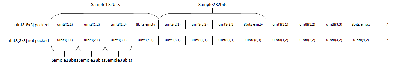
This figure shows how data is aligned for a signal with data type
uint8[8x3]. When the data is packed, three 8-bit
words are concatenated and extended by 8 bits to a 32-bit word. When the
data is not packed, each 8-bit word is represented as an 8-bit sample.
The combined width of the flattened signal must not exceed 512 bits.
Dependencies
This parameter is not visible when the Channel
type parameter is set to Software to
AXI4-Stream via DMA.
Read data signal
Select this box to use the same dimensions and data type for the reader and the writer of this channel. Clear the box to customize different settings for the reader and the writer. Clear the box to customize different dimensions and data type for the reader and writer interfaces.
rdData can be a multidimensional array. Specify the dimension for the array as a whole number.
When Channel type is set to
AXI4-Stream to Software via DMA, the
Dimensions parameter must be scalar.
Example: 1 – a scalar sample.
Example: [10 1] – a vector of ten scalars.
Example: [1080 1920 3] – a 1080p frame. The frame includes 1080 lines of 1920 pixels per line, and each pixel is represented by three values (for red, green and blue).
Dependencies
To enable this parameter, clear the Output data signal matches input check box.
Specify the data type of the rdData port. For help, click the ... button. This expands the menu and shows a Data Type Assistant.
When the Channel
type parameter is set to AXI4-Stream to
Software via DMA, the data type must be set to
uint16, uint32,
uint64, or
fixdt(0,128,0).
Dependencies
To enable this parameter, clear the Output data signal matches input check box.
Specify a time interval in seconds to define how often the block updates.
Specify the Sample time parameter as a scalar
when you do not want the output to have a time offset. To add a time
offset to the output, specify the Sample time
parameter as a 1-by-2 vector where
the first element is the sampling period and the second element is the
offset. For more information about sample times in Simulink, see Specify Sample Time.
Dependencies
To enable this parameter, do one of the following:
Set Channel type to
Software to AXI4-stream via DMA.Set Channel type to
AXI4 Random Accessand clear the Output data signal matches input check box.
Select this parameter to enable data packing across the last dimension
of the signal. The Memory Channel block packs the data
along the last dimension of the signal. For example, if the channel data
type is uint32, the dimensions are [1024
4], and if you select this parameter, then the memory
channel generates 1024 read or write transactions of 128 bits. For this
example, if you clear this sample packing parameter, the memory channel
generates 4096 transactions of 32 bits each.
This figure shows how data is aligned for a signal with data type
fixdt10[4x3]. When the data is packed, three
10-bit words are concatenated and extended by 2 bits to a 32-bit word.
When the data is not packed, each 10-bit word is extended to a 16-bit
word.
This figure shows how data is aligned for a signal with data type
uint8[8x3]. When the data is packed, three 8-bit
words are concatenated and extended by 8 bits to a 32-bit word. When the
data is not packed, each 8-bit word is represented as an 8-bit sample.
The combined width of the flattened signal must not exceed 512 bits.
Dependencies
To enable this parameter, clear Output data signal
matches input check box, and set Channel
type to a value other than AXI4-Stream
to Software via DMA.
Select this box to make the reader inherit the sample time offset from the writer. Clear the box to use a different sample time offset from the writer. For more information about sample time offsets, see Sample Time Offset.
Dependencies
To enable this parameter, clear the Output data signal matches input check box and set Channel type to one of the following values:
AXI4-Stream FIFOAXI4-Stream Video FIFOAXI4-Stream Video Frame Buffer
Select this box to use the pixel clock sample time. To use the pixel clock sample time, you must use scalar pixel dimensions. It is only relevant when streaming pixels. If both the reader and the writer are streaming frames, you get an error when checking this box.
Note
If both reader and writer are using framed signals, the signal dimensions are not scalar and pixel timing cannot be inferred. Selecting Use pixel clock sample times in this case creates an error.
Dependencies
To enable this parameter, set Channel type
to AXI4-Stream Video FIFO or
AXI4-Stream Video Frame
                                Buffer
.
For video-streaming applications, Frame size can often be inferred, and this parameter shows as a read-only value. When it cannot be inferred, select the Frame size from a drop-down menu.
When the reader or the writer are using framed signals of a frame with known porch and blanking timings, the Frame size is inferred from those timings. When the reader or the writer is a scalar and the other is a non-standard frame size, the Frame size cannot be inferred and you get an error.
When Channel type is set to
AXI4-Stream Video Frame Bufferand both reader and writer are using scalar dimensions for pixel streams, Frame size is inferred from BufferSize and TDATA and it is then a read-only value.When Channel type is set to
AXI4-Stream Video FIFOand both reader and writer are using scalar dimensions for pixel streams, select the Frame size as one of these values:160x120p480p SDTV (720x480p)576p SDTV (720x576p)720p HDTV (1280x720p)1080p HDTV (1920x1080p)320x240p640x480p800x600p1024x768p1280x768p1280x1024p1360x768p1400x1050p1600x1200p1680x1050p1920x1200p16x12p (test mode)
Dependencies
To enable this parameter, set Channel type
to AXI4-Stream Video FIFO or
AXI4-Stream Video Frame Buffer, and
select Use pixel clock sample times.
Performance
Clicking the button opens Performance plots for the memory channel in a new window. For more information about performance graphs, see Simulation Diagnostics.
Dependencies
To enable this parameter, select Enable memory simulation.