AXI4-Stream Video Interface
Using SoC Blockset™, you can implement a simplified, streaming pixel protocol in your model. Use HDL Coder™ to generate an HDL IP core with AXI4-Stream Video interfaces.
Streaming Pixel Protocol
You can use the streaming pixel protocol for AXI4-Stream Video interface mapping. Video algorithms process data serially and generate video data as a serial stream of pixel data and control signals.
To generate an IP core with AXI4-Stream Video interfaces, in your DUT interface, implement these signals:
Pixel Data
Pixel Control Bus
The Pixel Control Bus is a bus that has these signals:
hStarthEndvStartvEndvalid
The signals hStart and hEnd represent the start of an active line and the end of an active line respectively. The signals vStart and vEnd represent the start of a frame and the end of a frame.
You can optionally model the backpressure signal, Ready, and map it to the AXI4-Stream Video interface.
Protocol Signals and Timing Diagrams
This figure is a 2–by–3 pixel image. The active image area is the rectangle with a dashed line around it and the inactive pixels that surround it. The pixels are labeled with their grayscale values.
![]()
Pixel Data and Pixel Control Bus
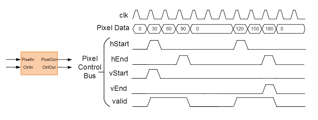
This figure shows the timing diagram for the Pixel Data and Pixel Control Bus signals that you model at the DUT interface.

The Pixel Data signal is the primary video signal that is transferred across the AXI4-Stream Video interface. When the Pixel Data signal is valid, the valid signal is asserted.
The hStart signal becomes high at the start of the active lines. The hEnd signal becomes high at the end of the active lines.
The vStart signal becomes high at the start of the active frame in the second line. The vEnd signal becomes high at the end of the active frame in the third line.
Optional Ready Signal
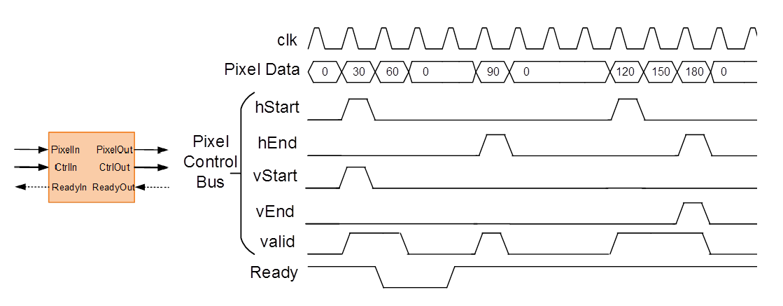
This figure shows the timing diagram for the Pixel Data, the Pixel Control Bus, and the Ready signal that you model at the DUT interface.

When you map the DUT ports to an AXI4-Stream Video interface, you can optionally model the backpressure signal, Ready, and map it to the AXI4-Stream Video interface.
In a Slave interface, with the Ready signal, you can apply back pressure. In a Master interface, with the Ready signal, you can respond to back pressure.
If you model the Ready signal in your AXI4-Stream Video interfaces, your Master interface must deassert its valid signal one cycle after the Ready signal is deasserted.
If you do not model the Ready signal, HDL Coder generates the associated backpressure logic.
See Also
AXI4 Video Frame Buffer | Memory Channel | SoC Bus Creator