Main Content

Memory Controller

Arbitrate memory transactions for one or more Memory Channel blocks

Since R2019a

  • Memory Controller block

Libraries:
SoC Blockset / Memory

Description

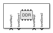
The Memory Controller block arbitrates between masters and grants them unique access to shared memory. Configure this block to support multiple channels with various arbitration protocols. The Memory Controller block is also instrumented to log and display performance data, enabling you to debug and understand the performance of your system at simulation time.

The following image shows the implementation of the Memory Controller block.

The numbers in the image represent different latency stages of the block.

  1. A burst-request enters the block.

  2. The request may be delayed by arbitration until it is granted access to the bus. Set the arbitration policy in Interconnect arbitration.

  3. If your model requires an additional delay before the first transfer starts, set that value in Request to first transfer (in clocks).

  4. The burst execution latency is calculated by the burst size, the data-width, the clock frequency, and the Bandwidth derating (%) value.

  5. If your model requires a delay from burst completion until a burst response is issued to the channel, set that value in Last transfer to transaction complete (in clocks).

The memory controller has an internal state, which is visible when using a Logic Analyzer to view simulation and execution metrics. The state values are:

  • BurstIdle: At start of simulation, before the block receives a burst request.

  • BurstRequest: A burst request enters the block.

  • BurstAccepted: The arbiter accepted the burst for processing.

  • BurstExecuting: A burst is executing.

  • BurstDone: A burst request is done executing.

  • BurstComplete: A burst response is done, and the burst is complete. The burstDone signal is now sent to the master.

For information about visualizing memory controller latencies, see Memory Controller Latency Plots.

Limitations

Ports

Input

expand all

This port receives requests for memory access as messages. Connect this input port to one of the burst request message ports (wrBurstReq or rdBurstReq) from a Memory Channel or Memory Traffic Generator block. For more information on messages, see Messages.

The number of burstReqN input ports is defined by the Number of masters parameter. burstReqN represents the Nth input port.

Data Types: BurstRequest2BusObj

Output

expand all

After a master is granted access to the memory and the burst transaction has completed, this port sends a message that the transaction completed. Memory access is then given to the next master according to the arbitration scheme. For more information on messages, see Messages.

The number of burstDoneN output ports is defined by the Number of masters parameter. burstDoneN represents the Nth input port

Data Types: BurstRequest2BusObj

Parameters

expand all

This parameter is read-only.

This parameter shows a link to the selected hardware board. Click the link to open the configuration parameters, and adjust the settings or choose a different board.

To learn more about configuration parameters for the memory controller, see FPGA design (PS mem controllers).

Main

Select between processing subsystem (PS) or programming logic (PL) memory.

  • If the selected board supports only a PL memory, then the default value is PL memory.

  • If the selected board supports only PS memory or only PL memory, then this parameter is read-only.

  • If the selected board is not a supported SoC board, then this parameter is not visible.

Set this parameter to generate the interface accordingly, and specify how many masters connect to the memory.

Advanced

Set the arbitration policy for the memory-interconnect block. When multiple masters request for memory access, the policy is determined by the value of this parameter.

  • Round robin sets a fair arbitration based on last service time.

  • Fixed port priority sets a fixed priority of burstReq1, burstReq2, burstReq3, and so on, where burstReq1 gets the highest priority.

Select this parameter to use the same model-wide settings as set in the configuration parameters. Clear this parameter to customize the settings for this memory controller. When using customized settings, values are still checked against hardware-specific constraints. For more information, see FPGA design (mem controllers).

This parameter is read-only.

This value shows the calculated bandwidth between the memory controller and the external memory. It is calculated as Frequency (MHz) multiplied by Data width (bits).

The clock rate of the bus used to drive interactions with the external memory. The controller frequency determines the overall system bandwidth for external memory that must be shared among all the masters in the model.

Dependencies

To enable this parameter, clear the Use hardware board settings parameter.

Set the width, in bits, of the datapath between the memory controller and the memory interconnect.

Dependencies

To enable this parameter, clear the Use hardware board settings parameter.

Model memory transaction inefficiencies specified by a derating percentage value. For every 100 clocks, memory transaction execution is paused for the number of clocks equal to Bandwidth derating. To set this parameter, measure the maximum bandwidth on your board and reflect the bandwidth derating from your board in this parameter. See an example in Analyze Memory Bandwidth Using Traffic Generators.

Dependencies

To enable this parameter, clear the Use hardware board settings parameter.

Specify the delay, in clock cycles, between a read or write request and the start of a transfer. Specify nonnegative integer values in both Write and Read boxes.

This delay is the number of clock cycles between making a request to the memory controller and until it returns a response. It is reflected in the Logic Analyzer waveforms as the time that the memory controller state remains as BurstAccepted. For more information about viewing waveforms in simulation, see Buffer and Burst Waveforms.

To set this value, measure the clock cycles between the burst-request and start of transfer on your board. For instructions for extracting this information from a hardware execution, see Configuring and Querying the AXI Interconnect Monitor.

Dependencies

To enable this parameter, clear the Use hardware board settings parameter.

Specify the delay in clock cycles between the end of a memory transfer and the end of a transaction. Specify nonnegative integer values in both Write and Read boxes.

To set this value, measure the clock cycles between the end of the burst and the completion of the transaction on your board. For instructions for extracting this information from a hardware execution, see Configuring and Querying the AXI Interconnect Monitor.

Dependencies

To enable this parameter, clear the Use hardware board settings parameter.

Performance

Click Launch performance app to open the Performance Metrics window. For additional information, see Simulation Performance Plots.

Extended Capabilities

Fixed-Point Conversion
Design and simulate fixed-point systems using Fixed-Point Designer™.

Version History

Introduced in R2019a