Main Content

Interrupt Channel

Send interrupt to processor from hardware

Since R2020b

  • Interrupt Channel block

Libraries:
SoC Blockset / Memory

Description

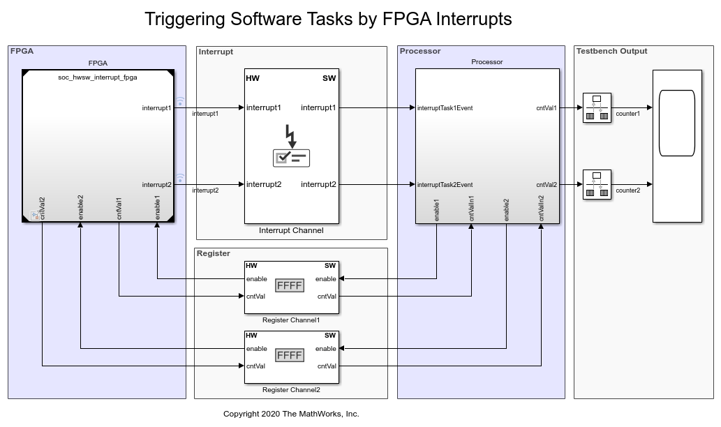
The Interrupt Channel block receives interrupt requests from FPGA logic or the Memory Channel block, arbitrates the requests, and triggers an event-driven software task to the Task Manager block. You can connect up to 16 devices to the interrupt controller, with one interrupt per device. The block consists of these three parts:

  • Interrupt Controller – This part accepts interrupt requests (IRQs) and arbitrates them according to a user-specified priority. When concurrent requests to the interrupt controller exist, requests with a higher priority are processed before those with a lower priority.

  • Kernel Interrupt Service Routine (ISR) – This part receives an interrupt request from the Interrupt Controller, serves the interrupt, and sends an acknowledge signal back to the Interrupt Controller, so that it can process the next IRQ.

  • IPCore Driver (one per interrupt) – This part receives a request from the Kernel ISR and triggers an event-driven task in the processor.

Even though the interrupt channel can have more than one interrupt output toward the processor, it sends no more than one active interrupt event to the processor at any given time.

This image shows a conceptual view of an Interrupt Channel block, that accepts interrupt requests from an FPGA algorithm. After arbitration, the kernel serves the request and triggers an event to a processor algorithm.

Interrupt Channel Structure

Examples

Ports

Input

expand all

Each interrupt is assigned a port pair: one input port and one output port. By default, the Nth interrupt port is named interruptN. You can change interrupt names by clicking Edit in the Interrupts parameter.

Connect this port to a Boolean signal from the FPGA logic or an event from a Memory Channel or Event Source block.

Dependencies

The number of input ports depends on the number of interrupts in the interrupt table.

Data Types: rteEvent | Boolean

Output

expand all

Each interrupt is assigned a port pair: one input port and one output port. By default, the Nth interrupt port is named interruptN. You can change interrupt names by clicking Edit in the Interrupts parameter.

Connect this port to a task event input port in the Task Manager block.

Dependencies

The number of output ports depends on the number of interrupts in the interrupt table.

Data Types: rteEvent

Parameters

expand all

This parameter includes a table, where each of its lines corresponds to an interrupt in the Interrupt Channel block. Edit the table to add or edit an interrupt. The interrupt channel can have up to 16 interrupts.

For each interrupt, you can edit these values.

  • Interrupt Name – Specify the interrupt name. This value changes the input and output port names for this interrupt.

  • Trigger Type – Select the trigger type for the interrupt by choosing either of these options.

    • Rising edge – When the interrupt originates in FPGA logic

    • SoC event – When the interrupt originates in the Memory Channel block or Event Source block

  • Priority – Set the priority for each interrupt is set in the Priority column. This value remains static. The top row represents the highest interrupt. Click Move Up to increase the priority of an interrupt. Click Move Down to decrease the priority of an interrupt.

This sample time represents the time required for the interrupt channel to arbitrate and execute an interrupt request. It is defined as the time required for the Interrupt Controller arbitration, Kernel ISR execution, and additional delay for the device driver.

Specify the processing time by entering a number, in seconds.

Extended Capabilities

Fixed-Point Conversion
Design and simulate fixed-point systems using Fixed-Point Designer™.

Version History

Introduced in R2020b