Cable Parameter Calculator
(To be removed) Compute RLC matrices and frequency-dependent parameters of cable arrangement
Since R2022b
The Specialized Power Systems library will be removed in R2026a. Use the Simscape™ Electrical™ blocks and functions instead. For more information on updating your models, see Upgrade Specialized Power Systems Models to use Simscape Electrical Blocks.
Description
The Cable Parameter Calculator app computes the RLGC matrices and the WB frequency-dependent cable parameters of a group of aerial cables, underground cables, or cables in a metal pipe. The cables are single-core and can made up of any number of concentric conductors and insulators.
The parameters computed by the app can be used in the PI Section Line block, Distributed Parameter Line block, and Distributed Parameter Line Frequency Dependent Line block to model a single-phase or multi-phase cable arrangement.
Open the Cable Parameter Calculator App
powergui Block Parameters dialog box: On the Tools tab, click Cable Parameter Calculator.
MATLAB® command prompt: Enter
powerCableParameters.
Parameters
Menu
Load typical cable parameters provided with Simscape
Electrical Specialized Power Systems software. This command opens a browser window
where you can select typical underground, aerial, or pipe cable configurations. By
default, the app is configured with the parameters of the
Param_4cablesUnderground2cond.mat file.
Opens a browser window where you can select your own cable data. Select the desired MAT file.
Saves your cable data by generating a MAT file that contains the app information and cable data.
The Cable Configuration table assumes that the cables are
buried below the ground level. Any previous edited parameters in the table are lost. The
position of the cables is specified by V (m) and H
(m) parameters. Aerial cables cannot be defined in this configuration. The
title of the table is Cable Configuration: Underground. Default
configuration of the app.
Note
If you set this configuration, you must possess a license for Optimization Toolbox™ to simulate your model.
The Cable Configuration table assumes that the cables are
aerial. Any previously edited parameters in the table are lost. The position of the
cables is specified by V (m) and H (m)
parameters. Underground cables cannot be defined in this configuration. The title of the
table is Cable Configuration: Aerial.
The Cable Configuration table assumes that the cables are
inside a metallic pipe. Any previously edited parameters in the table are lost. The
position of the cables is specified by X (m) and Angle
(deg) parameters. Aerial and underground cables cannot be defined in this
configuration. The title of the table is Cable Configuration: Inside a
pipe.
Open the documentation page of the app.
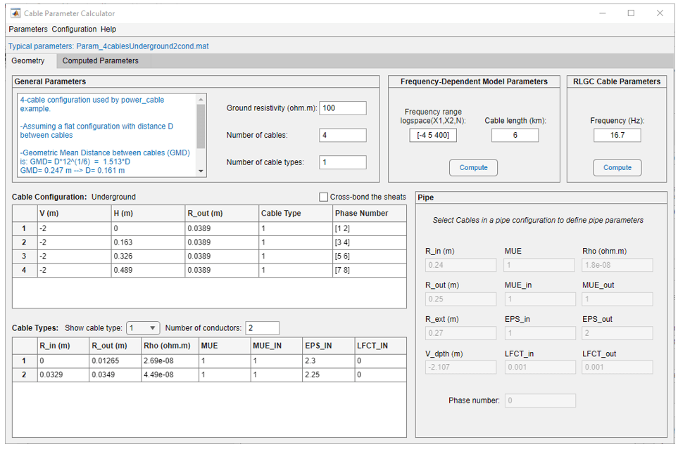
Geometry Tab
General Parameters
Free space to write comments related to the cable arrangement modeled by the app.
Ground resistivity in ohm-meters.
Specify how many cables are in the cable configuration. A cable is an arrangement of concentric conductors separated with insulators.
If you increase the value of the Number of Cables parameter, additional lines are added to the Cable Configuration table. The App automatically duplicate the parameter values of the last cable in the table and increment the Phase Number values accordingly. Depending on the cable configuration, the H (m) parameter value or the Angle (deg) parameter value is computed to not overlap position of other cables in the table.
Number of cable types. Specify how many different types of cables you have in your cable arrangement.
Frequency-Dependent Model Parameters
Specify a vector of three elements to define a frequency vector in the logspace(X1, X2,N) format, consisting of N logarithmically equally spaced points between 10^X1 and 10^X2.
Specify the length of the cable arrangement in kilometers. All the cables contained in the arrangement have the same length.
Computes the WB structure variable that contains the frequency-dependent parameters for the cable model. RLGC matrices are also computed at the frequency specified in the Frequency (Hz) parameter. After computing the parameters, the app displays the results in the Computed Parameters tab.
RLGC Cable Parameters
Frequency in hertz that is used to evaluate RLC parameters.
Computes the R, L, G and C matrices for a given cable. After computing the parameters, the app displays the results in the Computed Parameters tab.
Cable Configuration Table
When selected the elements of the RLGC matrices are averaged to reflect cross-bonding the sheaths. The sheath conductors correspond to the conductor no.2 of the cables. The cable can have more than two conductors; however, to use the option all the additional conductors (3,4, …) of each cables need to be grounded, i.e., associated to phase number 0 in the Phase Number parameter vector.
The electric power losses in a cable system dependent on the induced currents flowing in the metallic sheaths. These induced currents depend on the coupling between phase and sheath conductors. For example, in a three-phase cable, if sheaths are not cross-bonded a flat formation will produce higher induced sheath voltages than a trefoil formation. This will in turn result in higher sheath circulating currents and higher losses if the sheaths are bonded (grounded) at both ends. To decrease sheath induced voltage and currents, cross-bonding of sheaths is performed on minor cable sections, like transposition of three-phase aerial transmission lines.
Select this option as an alternative to model all minor sections of cables with physical transposition of sheaths. This will result in approximately same induced voltage and currents in the sheaths while simulating much faster because the model size is reduced, and a longer cable length allows using a larger sample time.
Dependencies
To enable this parameter,
All the cables in the Cable Configuration table must be set to the same Cable Type value.
The Cable Type value must correspond to a cable type having two or more conductors.
All conductors outside the sheath must be grounded (Phase Number value set to 0).
Vertical position of the center of the cable.
When you select Aerial cables configuration in the Configuration menu, all the V values in the table must be finite positive values. When you select Underground cables configuration in the Configuration menu, all the V values in the table must be finite negative values.
The app does not allow a mix of aerial and underground cables.
Dependencies
To enable this parameter, select Aerial cables or Underground cables options in the Configuration menu.
Represent the horizontal position of the cable.
H value can be negative, 0, or positive. You can define the horizontal mark position 0 anywhere in your cable arrangement and define the position of the cables according to this mark. For example, the position 0 can be defined in the center of the cable arrangement, so the cables placed on the left will have a negative H (m) value and those on the right will have a positive H (m) value.
Dependencies
To enable this parameter, select Aerial cables or Underground cables options in the Configuration menu.
Cable position relative to the center of the pipe, in meters.
Specify the position of the center of the cable relative to the center of the pipe.

Dependencies
To enable this parameter, select Cables in a pipe in the Configuration menu.
Position angle of the cable inside the pipe, in degrees.
Specify the angle of the imaginary line that represent the distance between the center of the pipe and the center of the cable.

Dependencies
To enable this parameter, select Cables in a pipe in the Configuration menu.
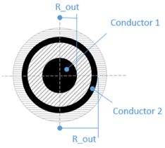
External radius of the cable.
The radius of the of the outer insulation of the cable.
Value corresponding to the cable type number defined in the Cable types table.
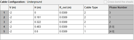
Associate each conductor of the cable to the electrical phases of the network. All the conductors for all the cables in the cable configuration need to be associated to an unique phase number. The only exception is phase 0 (meaning that the conductor is grounded) that can be specified for several conductors in several cables.
Phase numbers start with 1 (or 0 if you have grounded conductors) and increase consecutively. The phase numbers do not need to be specified in the numerical order in the table. For example, the following configuration is correct: we have a total of 7 conductors; two are grounded, and all the other conductors are uniquely attributed to a phase number 1,2,3,4, and 5 :
Cable Types Table
Select the cable type number and the Cable Types table will show its parameters. The drop-down menu lists all the cable type numbers, from 1 to Number of cable types.
Specify how many concentric conductors exist in the selected cable. When the number of conductors parameter is increased, the app automatically adds a new line in the table with similar parameters as of the previous conductor, and it resizes the R_in and R_out dimensions proportionally..
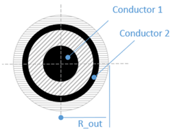
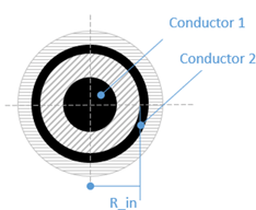
Inside radius of the conductor.
Specify the distance from the center of the cable to the inner part of the conductor. For the first conductor, this value is usually set to 0.
Outside radius of the conductor.
Specify the distance from the center of the cable to the outer part of the conductor.
Conductor resistivity.
The resistivity of the conductor in ohm.m
Conductor relative permeability.
The relative permeability of the conductor.
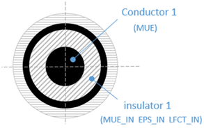
Surrounding insulation relative permeability.
The relative permeability of the insulation that is surrounding the conductor.
Surrounding insulation relative permittivity.
The relative permittivity of the insulation that surrounds the conductor.
Surrounding insulation loss factor.
The loss factor of the insulation that is surrounding the conductor.
A loss factor of 0.001 means that the active power losses (in watts) inside the dielectric is the 0.1% of the reactive power (in vars) associated with the Conductor1-Conductor 2 capacitance.
Pipe Parameters
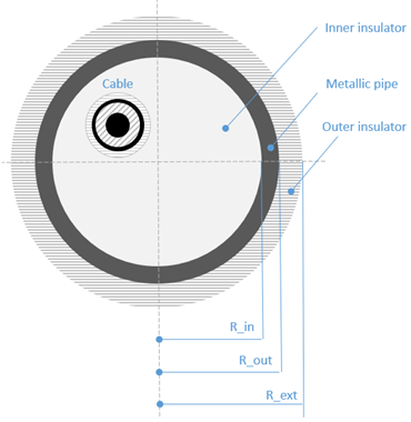
Internal radius of the metallic pipe in meters.
External radius of the metallic pipe in meters.
External radius of the outer insulator.
Depth of center of the pipe below the ground level.
Metallic pipe relative permeability.
Inside insulation relative permeability.
Inside insulation relative permittivity.
Inside insulation loss factor.
Pipe resistivity.
The resistivity of the metallic pipe.
Outside insulation relative permeability.
Outside insulation relative permittivity.
Outside insulation loss factor.
Phase number connected to the metallic pipe.
Specify a value of 0 to connect the metallic pipe to the electrical ground. Specify a positive integer value between 1 and N+1, where N is the maximum phase number value that is specified in the Phase Number column of the Cable Configuration table.
Computer Parameters Tab
Display the R, L, G, and C matrices resulting of the Compute buttons.
Sends the R, L, G, C , and WB parameters to the MATLAB workspace. The app creates the variables R, L, G, C, and WB in your workspace.
Confirms the block selection. The name of the selected block appears in the Send to block edit parameter.
Edit box to either manually specify the name of a PI Section Line block, Distributed Parameters Line, or Distributed Parameters Line Frequency Dependent block where the RLGC or WB parameters will be sent when the user click the Send button. By default, it displays: – No block specified, and the Send button is grayed out and unavailable.
Sends the RLC parameters to the Distributed Parameter Line or Pi Section Line blocks specified in the Send to block parameter. Send the WB parameters via a mat file to the Distributed Parameter Line Frequency Dependent block specified in the Send to block parameter.
Version History
Introduced in R2022b