Synchronous Machine pu Fundamental
(To be removed) Model dynamics of three-phase round-rotor or salient-pole synchronous machine using fundamental parameters in pu units
The Specialized Power Systems library will be removed in R2026a. Use the Simscape™ Electrical™ blocks and functions instead. For more information on updating your models, see Upgrade Specialized Power System Models to use Simscape Electrical Blocks.
Libraries:
Simscape /
Electrical /
Specialized Power Systems /
Electrical Machines
Description
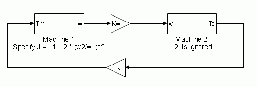
The Synchronous Machine pu Fundamental block models a synchronous machine in generator or motor mode using fundamental parameters in pu units. The operating mode is dictated by the sign of the mechanical power (positive for generator mode or negative for motor mode). The electrical part of the machine is represented by a sixth-order state-space model and the mechanical part is the same as in the Simplified Synchronous Machine block.
For more information on the pu units system, see Per-Unit System of Units.
The model takes into account the dynamics of the stator, field, and damper windings. The equivalent circuit of the model is represented in the rotor reference frame (the qd frame). Stator windings are connected in wye to an internal neutral point. All rotor parameters and electrical quantities are viewed from the stator and identified by primed variables. The subscripts are:
d,q — d- and q-axis quantity
R,s — Rotor and stator quantity
l,m — Leakage and magnetizing inductance
f,k — Field and damper winding quantity
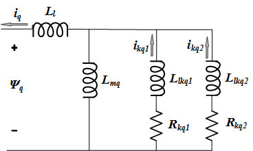
The electrical model of the machine is shown in these diagrams.

Dynamic Model with Unequal Mutual Inductance
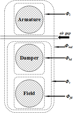
The conventional theory of synchronous machine modeling for stability analysis assumes that the mutual inductances between the armature, damper, and field on direct-axis windings are identical. Generally, damper windings are near the air gap, and as a result the flux linking damper circuits are almost equal to the flux linking armature. This hypothesis produces acceptable outcomes for a wide range of stability studies, especially those on the side of the network. However, when it comes to field current studies, there is considerable error. The equivalent circuit dynamic model of a synchronous machine may include an additional inductance representing the difference between field-damper and field-armature mutual inductances on the D-axis [1]. This inductance is typically called Canay inductance. Canay inductance corresponds to the leakage flux, ΦC, in the following figure and is interpreted as a corrective element in an equivalent model that may have a negative value [2].

The IEEE® standard 1110-2002 [3] presents the direct and quadratic axes of the synchronous machine dynamic model as shown in the diagrams.


The relevant equations are:
Base Values and Transformation Ratio
The Synchronous Machine pu Fundamental block allows you to specify the fundamental parameters of a synchronous machine. You enter field and damper winding parameters (resistances, leakage inductances, and mutual inductances) in pu.
This table displays the stator base values.
| Base stator voltage = peak nominal line-to-neutral voltage (V) |
| Base stator current (A) |
| Base stator impedance (Ω) |
| Base angular frequency (rad/s) |
| Base stator inductance (H) |
where:
Pn is the three-phase nominal power (VA).
Vn is the nominal line-to-line voltage (Vrms).
fn is the nominal frequency (Hz).
ifn is the nominal field current producing nominal stator voltage at no load (A).
The stator parameters to specify in the block are:
| Stator resistance per phase (pu) |
| Stator leakage inductance (pu) |
| Direct-axis magnetizing inductance (pu) |
| Quadrature-axis magnetizing inductance (pu) |
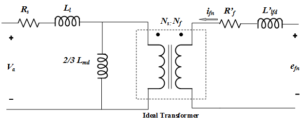
This figure shows one phase of the stator winding coupled with the field winding.

In the diagram:
Ns and Nf are the equivalent number of sinusoidally distributed turns of the stator winding and of the field winding, respectively.
Rs and Ll are stator resistance and leakage inductance.
Rf′ and Llfd′ are field resistance and leakage inductance.
When the three stator windings are energized with a three-phase positive-sequence voltage and the field winding is open, the stator magnetizing inductance is Lmd. However, when only one phase is energized and the field winding is open, the magnetizing inductance is 2/3 Lmd, as shown in the figure.
At no load, when the field winding is rotating at nominal speed and bears the nominal field DC current ifn, the amplitude of AC voltage (peak value) induced on one phase of the stator is Vsbase.
The maximum mutual inductance between one stator winding and the field winding is obtained when the two windings are aligned and is given by:
from which we deduce the transformation ratio:
The transformation ratio can be also expressed as:
where Ifbase is the base field current. The table shows how to compute field base values.
| Base field current (A) |
| Base field voltage (V) |
| Base field impedance (Ω) |
| Base field inductance (H) |
The actual field parameters are:
Rf′ is field resistance (Ω)
Llfd′ is field leakage inductance (H)
The field parameters to enter in the block menu are:
| Field resistance (pu) |
| Field leakage inductance (pu) |
The voltage at the Vf input of the block is normalized with respect to nominal field voltage so that a 1 pu input produces a 1 pu stator voltage at no load. The If current returned by the measurement output of the block is also normalized with respect to the nominal field current so that a 1 pu input produces If = 1 pu.
Assumptions and Limitations
In discrete systems, when you set the Discrete solver model parameter
of a Synchronous Machine block to Trapezoidal non
iterative, you might have to connect a small parasitic resistive load
at the machine terminals to avoid numerical oscillations. Large sample times require
larger loads. The minimum resistive load is proportional to the sample time. As a rule
of thumb, remember that with a 25 μs time step on a 60 Hz system, the minimum load is
approximately 2.5% of the machine nominal power. For example, a 200 MVA synchronous
machine in a power system discretized with a 50 μs sample time requires approximately 5%
of resistive load or 10 MW. If the sample time is reduced to 20 μs, a resistive load of
4 MW should be sufficient.
However, if you set the Discrete solver model parameter of a
Synchronous Machine block to Trapezoidal iterative (alg.
loop), you can use a negligible parasitic load (below 0.1% of nominal
power) while preserving numerical stability. This iterative model produces an algebraic
loop and results in slower simulation speed.
Ports
Input
Output
Conserving
Parameters
References
[1] Canay, I.M. "Causes of Discrepancies on Calculation of Rotor Quantities and Exact Equivalent Diagrams of the Synchronous Machine." IEEE Transactions on Power Apparatus and Systems. PAS-88, no. 7 (1969): 1114–1120.
[2] Moeini, A., et al. “Synchronous Machine Stability model, an Update to IEEE Std 1110-2002 Data Translation Technique.” IEEE standards panel sessions. 2018.
[3] IEEE Guide for Synchronous Generator Modeling Practices and Applications in Power System Stability Analyses. IEEE Std 1110-2002 (Revision of IEEE Std 1110-1991 [2003]): 1–72.
[4] Krause, P.C. Analysis of Electric Machinery. Section 12.5. New York: McGraw-Hill, 1986.
[5] Kundur, P. Power System Stability and Control. New York, McGraw-Hill, 1994.
Extended Capabilities
Version History
Introduced before R2006a


