Build and Simulate a Simple Circuit Using Specialized Power Systems
Introduction
Simscape™ Electrical™ Specialized Power Systems allows you to build and simulate electrical circuits containing linear and nonlinear elements.
In this section, you
Explore the Simscape Electrical Specialized Power Systems library.
Learn how to build a simple circuit from the Simscape Electrical Specialized Power Systems library.
Interconnect Simulink® blocks with your circuit.
The circuit in the figure represents an equivalent power system feeding a 300-km transmission line. The line is compensated by a shunt inductor at its receiving end. A circuit breaker allows energizing and de-energizing of the line. To simplify matters, only one of the three phases is represented. The parameters shown in the figure are typical of a 735-kV power system.
Circuit to Be Modeled

Building the Electrical Circuit with the Simscape Electrical Specialized Power Systems Library
The graphical user interface uses Simulink functionality to interconnect various electrical components. The electrical components are grouped in the Simscape Electrical Specialized Power Systems library.
To open the Simscape Electrical Specialized Power Systems main library, at the MATLAB® command prompt, enter:
Open a new blank model to contain your first circuit and save it as
circuit1.Add the AC Voltage Source block from the Simscape > Electrical > Specialized Power Systems > Sources library.
Set the Amplitude, Phase, and Frequency parameters of the AC Voltage Source block according to the values shown in Circuit to Be Modeled.
The amplitude to be specified for a sinusoidal source is its peak value (424.4e3*sqrt(2) volts, in this case).
Change the name of this block from AC Voltage Source to Vs.
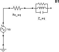
Add the Parallel RLC Branch block from the Simscape > Electrical > Specialized Power Systems > Passives library, set its parameters as shown in Circuit to Be Modeled, and name it Z_eq.
The resistance Rs_eq of the circuit can be obtained from the Parallel RLC Branch block. Duplicate the Parallel RLC Branch block, which is already in your circuit1 window. Select R for the Branch Type parameter and set the R parameter according to Circuit to Be Modeled.
Once the dialog box is closed, notice that the L and C components have disappeared so that the icon now shows a single resistor.
Name this block Rs_eq.
Resize the various components and interconnect blocks by dragging lines from outputs to inputs of appropriate blocks.
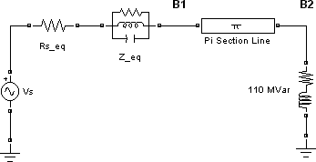
Add a PI Section Line block from the Simscape > Electrical > Specialized Power Systems > Power Grid Elements library. You add the circuit breaker later in Simulating Transients.
The model of a line with uniformly distributed R, L, and C parameters normally consists of a delay equal to the wave propagation time along the line. This model cannot be simulated as a linear system because a delay corresponds to an infinite number of states. However, a good approximation of the line with a finite number of states can be obtained by cascading several PI circuits, each representing a small section of the line.
A PI section consists of a series R-L branch and two shunt C branches. The model accuracy depends on the number of PI sections used for the model. Copy the PI Section Line block from the Simscape > Electrical > Specialized Power Systems > Power Grid Elements library into the circuit1 window, set its parameters as shown in Circuit to Be Modeled, and specify one line section.
The shunt reactor is modeled by a resistor in series with an inductor. You could use a Series RLC Branch block to model the shunt reactor, but then you would have to calculate and specify the R and L values manually based on the quality factor and reactive power specified in Circuit to Be Modeled.
Therefore, you might find it more convenient to use a Series RLC Load block that allows you to specify directly the active and reactive powers absorbed by the shunt reactor.
Add a Series RLC Load block from the Simscape > Electrical > Specialized Power Systems > Passives library. Name this block 110 Mvar. Set its parameters as follows:
Vn
424.4e3 Vfn
60 HzP
110e6/300 W(quality factor =300)QL
110e6varsQc
0As no reactive capacitive power is specified, the capacitor disappears on the block icon when the dialog box is closed. Interconnect the new blocks as shown.
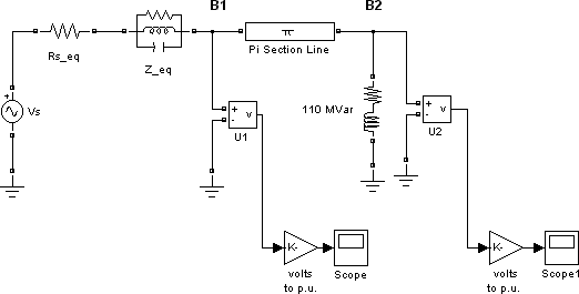
Add a Voltage Measurement block from the Simscape > Electrical > Specialized Power Systems > Sensors and Measurements library. Name it U1. Connect its positive input to the node B1 and its negative input to a new Ground block.
To observe the voltage measured by U1, a display system is needed.
Add a Scope block into your circuit1 window. If the scope were connected directly at the output of the voltage measurement, it would display the voltage in volts. However, electrical engineers in power systems are used to working with normalized quantities (per unit system). The voltage is normalized by dividing the value in volts by a base voltage corresponding to the peak value of the system nominal voltage. In this case, the scaling factor K is
Add a Gain block and set its gain as above. Connect its output to the Scope block and connect the output of the Voltage Measurement block to the Gain block. Duplicate this voltage measurement system at the node B2, as shown below.
Add a powergui block from the Simscape > Electrical > Specialized Power Systems library. The purpose of this block is discussed in Using the Powergui Block to Simulate Simscape Electrical Specialized Power Systems Models.
Start the simulation.
Open the Scope blocks and observe the voltages at nodes B1 and B2.
While the simulation is running, open the Vs block dialog box and modify the amplitude. Observe the effect on the two scopes. You can also modify the frequency and the phase. You can zoom in on the waveforms in the scope windows by drawing a box around the region of interest with the left mouse button.
Interfacing the Electrical Circuit with Other Simulink Blocks
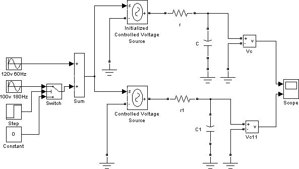
The Voltage Measurement block acts as an interface between the Simscape Electrical Specialized Power Systems blocks and the Simulink blocks. For the system shown above, you implemented such an interface from the electrical system to the Simulink system. The Voltage Measurement block converts the measured voltages into Simulink signals.
Similarly, the Current Measurement block from the Simscape > Electrical > Specialized Power Systems > Sensors and Measurements library can be used to convert any measured current into a Simulink signal.
You can also interface from Simulink blocks to the electrical system. For example, you can use the Controlled Voltage Source block to inject a voltage in an electrical circuit, as shown in the following figure.
Electrical Terminal Ports and Connection Lines
Simscape
Electrical Specialized Power Systems modeling environment is similar to that
of other products in the Physical Modeling family. Its blocks often feature both
normal Simulink input and output ports > and special electrical terminal ports ![]() :
:
Lines that connect normal Simulink ports
>are directional signal lines.Lines that connect terminal ports
 are special electrical connection
lines. These lines are nondirectional and can be branched, but you
cannot connect them to Simulink ports > or to normal Simulink signal lines.
are special electrical connection
lines. These lines are nondirectional and can be branched, but you
cannot connect them to Simulink ports > or to normal Simulink signal lines.You can connect Simulink ports
>only to other Simulink ports and electrical terminal ports only to other electrical terminal
ports.
only to other electrical terminal
ports.Converting Simulink signals to electrical connections or vice versa requires using a Simscape Electrical Specialized Power Systems block that features both Simulink ports and electrical terminal ports.
Some Simscape Electrical Specialized Power Systems blocks feature only one type of port.
Measuring Voltages and Currents
When you measure a current using a Current Measurement block, the positive direction of current is indicated on the block icon (positive current flowing from + terminal to – terminal). Similarly, when you measure a voltage using a Voltage Measurement block, the measured voltage is the voltage of the + terminal with respect to the – terminal.
Basic Principles of Connecting Capacitors and Inductors
Pay particular attention when you connect capacitor elements together with voltage sources, or inductor elements in series with current sources. When you start the simulation, the software displays an error message if one of the following two connection errors are present in your diagram:
You have connected a voltage source in parallel with a capacitor, or a series of capacitor elements in series, like in the two examples below.

To fix this problem, you can add a small resistance in series between the voltage source and the capacitors.
You have connected a current source in series with an inductor, or a series of inductors connected in parallel, like in the example below.
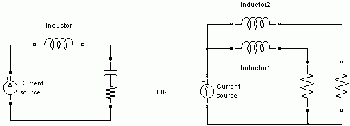
To fix this problem, you can add a large resistance in parallel with the inductor.
Using the Powergui Block to Simulate Simscape Electrical Specialized Power Systems Models
The Powergui block is the environment block for Simscape Electrical Specialized Power Systems models. It is used to store the equivalent Simulink circuit that represents the state-space equations of the Simscape Electrical Specialized Power Systems blocks. It also opens tools for steady-state and simulation results analysis and for advanced parameter design. When you start the simulation, you will get an error if no Powergui block is found in your model.
See powergui for more information on how to use the powergui block in your models.