Main Content

FEM-Parameterized Linear Actuator

Linear actuator defined in terms of magnetic flux

  • FEM-Parameterized Linear Actuator block

Libraries:
Simscape / Electrical / Electromechanical / Mechatronic Actuators

Description

The FEM-Parameterized Linear Actuator block implements a model of a linear actuator defined in terms of magnetic flux. Use this block to model custom solenoids and linear motors where magnetic flux depends on both distance asond current. You parameterize the block using data from a third-party magnetic finite-element method (FEM) package.

Note

To use this block to represent a solenoid with air gap x between case C and plunger R, then the tabulated force should be negative to represent the pulling force bringing R towards C.

The block has two options for the electrical equation. The first, Define in terms of dPhi(i,x)/dx and dPhi(i,x)/di, defines the current in terms of partial derivatives of the magnetic flux (Φ) with respect to distance (x) and current (i), the equations for which are:

didt=(viRΦxdxdt)/Φi

The second option, Define in terms of Phi(i,x), defines the voltage across the component directly in terms of the flux, the equation for which is:

v=iR+ddtΦ(x,i)

Numerically, defining the electrical equation in terms of flux partial derivatives is better because the back-emf is piecewise continuous. If using the flux directly, using a finer grid size for current and position will improve results, as will selecting cubic or spline interpolation.

In both cases, you have an option to either directly specify the force as a function of current and position, by using the Force matrix, F(i,x) parameter, or have the block automatically calculate the force matrix.

If entering the electromagnetic force data directly, you can either use data supplied by the finite element magnetic package (which you used to determine the flux) or calculate the force from the flux with following equation:

F=0iΦ(x,i)xdi

For an example that shows how to implement this type of integration in MATLAB®, see 
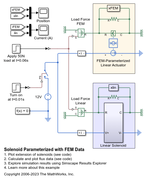
Solenoid Parameterized with FEM Data. The related file ee_solenoid_fem_params.m contains the code that calculates and plots the flux data.

Alternatively, the block can automatically calculate the force matrix from the flux information that you provide. To select this option, set the Calculate force matrix? parameter to Yes. The force matrix calculation occurs at model initialization based on current block flux linkage information. The force is calculated by numerically integrating the rate of change of flux linkage with respect to position over current, according to the preceding equation. If the Electrical model parameter is set to Define in terms of Phi(i,x), then the block must first estimate the Flux partial derivative wrt displacement, dPhi(i,x)/dx parameter value from the flux linkage data. When doing this, the block uses the interpolation method specified by the Interpolation method parameter. Typically, the Smooth option is most accurate, but the Linear option is most robust.

You can define Φ and its partial derivatives for just positive, or positive and negative currents. If defining for just positive currents, then the block assumes that Φ(–i,x) = –Φ(i,x). Therefore, if the current vector is positive only:

  • The first current value must be zero.

  • The flux corresponding to zero current must be zero.

  • The partial derivative of flux with respect to displacement must be zero for zero current.

To model a linear motor with a repeated flux pattern, set the Flux dependence on displacement parameter to Cyclic. When selecting this option, the force and flux (or force and flux partial derivatives depending on the option chosen) must have identical first and last columns.

Note

The actuated motion direction of this block can be swapped by flipping the block and swapping the R and C connections.

Model Thermal Effects

You can expose the thermal port to model the effects of losses that convert power to heat. To expose the thermal port, set the Modeling option parameter to either:

  • No thermal port — The block does not contain a thermal port.

  • Show thermal port — The block contains one thermal conserving port.

For more information about using thermal ports in actuator blocks, see Simulating Thermal Effects in Rotational and Translational Actuators.

Assumptions and Limitations

  • You must supply a consistent set of force and flux data. There is no check that ensures that the force matrix is consistent with the flux data.

  • When driving the FEM-Parameterized Linear Actuator block via a series inductor, you may need to include a parallel conductance in the inductor component.

Ports

Conserving

expand all

Electrical conserving port associated with the actuator positive terminal.

Electrical conserving port associated with the actuator negative terminal.

Mechanical translational conserving port associated with the actuator case.

Mechanical translational conserving port associated with the plunger.

Thermal port.

Dependencies

To enable this port, set Modeling option to Show thermal port.

Parameters

expand all

Whether to enable the thermal port of the block and model the effects of losses that convert power to heat.

Magnetic Force

Select one of the following parameterization options, based on the underlying electrical model:

  • Define in terms of dPhi(i,x)/dx and dPhi(i,x)/di — Define the current through the block in terms of partial derivatives of the magnetic flux with respect to distance and current.

  • Define in terms of Phi(i,x) — Define the voltage across the block terminals directly in terms of the flux.

Specify a vector of monotonically increasing current values corresponding to your force-flux data. If you specify positive currents only, the first element must be zero.

Specify a vector of monotonically increasing displacement values corresponding to your force-flux data.

Specify a matrix of the flux partial derivatives with respect to current. The default value, in Wb/A, is:

[ 0.104 0.098 0.091 0.085 0.078; 
0.095 0.089 0.084 0.079 0.073; 
0.085 0.081 0.077 0.073 0.069; 
0.076 0.073 0.07 0.067 0.064; 
0.067 0.065 0.063 0.061 0.06; 
0.057 0.057 0.056 0.056 0.055; 
0.048 0.049 0.049 0.05 0.05; 
0.038 0.04 0.042 0.044 0.046; 
0.029 0.032 0.035 0.038 0.041; 
0.02 0.024 0.028 0.033 0.037; 
0.01 0.016 0.021 0.027 0.032 ]

Dependencies

This parameter is visible only when you set the Electrical model parameter to Define in terms of dPhi(i,x)/dx and dPhi(i,x)/di.

Specify a matrix of the flux partial derivatives with respect to displacement. The default value, in Wb/m, is:

[ 0 0 0 0 0; 
-11.94 -10.57 -9.19 -7.81 -6.43; 
-21.17 -19.92 -18.67 -17.42 -16.16; 
-27.99 -26.87 -25.75 -24.62 -23.5; 
-32.42 -31.43 -30.43 -29.43 -28.44; 
-34.46 -33.59 -32.72 -31.85 -30.98; 
-34.09 -33.35 -32.61 -31.87 -31.12; 
-31.33 -30.72 -30.1 -29.49 -28.87; 
-26.17 -25.68 -25.2 -24.71 -24.22; 
-18.62 -18.26 -17.9 -17.54 -17.18; 
-8.66 -8.43 -8.2 -7.97 -7.73 ]

Dependencies

This parameter is visible only when you set the Electrical model parameter to Define in terms of dPhi(i,x)/dx and dPhi(i,x)/di.

Specify a matrix of the total flux linkage, that is, flux times the number of turns. The default value, in Wb, is:

[ 0 0 0 0 0; 
0.0085 0.0079 0.0075 0.0071 0.0067; 
0.0171 0.016 0.0151 0.0143 0.0137; 
0.0254 0.0239 0.0226 0.0215 0.0206; 
0.033 0.0312 0.0297 0.0283 0.0271; 
0.0396 0.0377 0.036 0.0345 0.0331; 
0.0452 0.0433 0.0415 0.0399 0.0384; 
0.0495 0.0478 0.0461 0.0446 0.0431; 
0.0526 0.0512 0.0498 0.0485 0.0472; 
0.0545 0.0537 0.0528 0.0519 0.0508; 
0.0554 0.0553 0.0551 0.0548 0.0542 ]

Dependencies

This parameter is visible only when you set the Electrical model parameter to Define in terms of Phi(i,x).

Specify the way of providing the electromagnetic force data:

  • No — Enter the electromagnetic force data directly, by using the Force matrix, F(i,x) parameter. This is the default option.

  • Yes — The block calculates the force from the flux linkage information, as a function of current and displacement.

Specify a matrix of the electromagnetic force applied to the plunger or moving part. The default value, in N, is:

[ 0 0 0 0 0; 
-0.6 -0.5 -0.4 -0.3 -0.3; 
-2.3 -2 -1.7 -1.4 -1.2; 
-4.9 -4.3 -3.7 -3.2 -2.7; 
-8.3 -7.3 -6.4 -5.5 -4.7; 
-12.2 -10.7 -9.4 -8.2 -7.2; 
-16.2 -14.4 -12.7 -11.3 -10; 
-20 -17.9 -15.9 -14.3 -12.9; 
-23.3 -20.9 -18.8 -17.1 -15.7; 
-25.7 -23.1 -21.1 -19.4 -18.2; 
-26.5 -24.1 -22.2 -20.9 -20.1 ]

Dependencies

This parameter is visible only when you set the Calculate force matrix? parameter to No.

Specify the flux pattern:

  • Unique — No flux pattern present.

  • Cyclic — Select this option to model a linear motor with a repeated flux pattern. The force and flux (or force and flux partial derivatives, depending on the Electrical model option chosen) must have identical first and last columns.

Select one of the following interpolation methods for approximating the output value when the input value is between two consecutive grid points:

  • Linear — Select this option to get the best performance.

  • Smooth — Select this option to produce a continuous surface with continuous first-order derivatives.

For more information on interpolation algorithms, see the PS Lookup Table (2D) block reference page.

Select one of the following extrapolation methods for determining the output value when the input value is outside the range specified in the argument list:

  • Linear — Select this option to produce a surface with continuous first-order derivatives in the extrapolation region and at the boundary with the interpolation region.

  • Nearest — Select this option to produce an extrapolation that does not go above the highest point in the data or below the lowest point in the data.

  • Error — Issues an error if the input signal is outside the range of the table. Select this option to avoid going into the extrapolation mode when you want your data to be within the table range.

For more information on extrapolation algorithms, see the PS Lookup Table (2D) block reference page.

Total resistance of the electrical winding.

Magnetizing resistance. The value must be greater than zero. The default value is inf, which implies that there are no iron losses.

Mechanical

Linear damping. The value can be zero.

Mass of the moving part, which corresponds to mechanical translational port R. The value can be zero.

The stroke at which the lower mechanical end stop is applied. The value can be -Inf.

The stroke at which the upper mechanical end stop is applied. The value can be Inf.

Contact stiffness between plunger and end stops.

Contact damping between plunger and end stops.

Temperature Dependence

This tab appears only for blocks with exposed thermal port.

Resistance temperature coefficient.

Temperature for which the actuator parameters are defined.

Thermal Port

This tab appears only for blocks with exposed thermal port.

Thermal mass is the energy required to raise the temperature by one degree.

Extended Capabilities

C/C++ Code Generation
Generate C and C++ code using Simulink® Coder™.

Version History

Introduced in R2010a