Light-Emitting Diode
Exponential light-emitting diode with optical power output port

Libraries:
Simscape /
Electrical /
Sensors & Transducers
Description
The Light-Emitting Diode block represents a light-emitting diode as an exponential diode in series with a current sensor. The optical power presented at the signal port W is equal to the product of the current flowing through the diode and the Optical power per unit current parameter value.
The exponential diode model provides this relationship between the diode current I and the diode voltage V:
where:
q is the elementary charge on an electron (1.602176e–19 Coulombs).
k is the Boltzmann constant (1.3806503e–23 J/K).
N is the emission coefficient.
IS is the saturation current.
Tm1 is the temperature at which you specify the diode parameters by using the Measurement temperature parameter value.
When (qV / NkTm1) > 80, the block replaces with (qV / NkTm1 – 79)e80, which matches the gradient of the diode current at (qV / NkTm1) = 80 and extrapolates linearly. When (qV / NkTm1) < –79, the block replaces with (qV / NkTm1 + 80)e–79, which also matches the gradient and extrapolates linearly. Typical electrical circuits do not reach these extreme values. The block provides this linear extrapolation to help convergence when solving for the constraints during simulation.
When you select Use parameters IS and N for the
Parameterization parameter, you specify the diode in terms of the
Saturation current IS and Emission coefficient N
parameters. When you select Use I-V curve data points for the
Parameterization parameter, you specify two voltage and current measurement
points on the diode I-V curve and the block derives the IS and
N values. When you specify current and voltage measurements, the block
calculates IS and N as follows:
where:
Vt = kTm1 / q.
V1 and V2 are the values in the Voltages [V1 V2] vector.
I1 and I2 are the values in the Currents [I1 I2] vector.
The exponential diode model provides the option to include a junction capacitance:
When you select
Fixed or zero junction capacitancefor the Parameterization parameter, the capacitance is fixed.When you select
Use parameters CJO, VJ, M & FCfor the Parameterization parameter, the block uses the coefficients CJO, VJ, M, and FC to calculate a junction capacitance that depends on the junction voltage.When you select
Use C-V curve data pointsfor the Parameterization parameter, the block uses three capacitance values on the C-V capacitance curve to estimate CJO, VJ, and M and uses these values with the specified value of FC to calculate a junction capacitance that depends on the junction voltage. The block calculates CJO, VJ, and M as follows:where:
VR1, VR2, and VR3 are the values in the Reverse bias voltages [VR1 VR2 VR3] vector.
C1, C2, and C3 are the values in the Corresponding capacitances [C1 C2 C3] vector.
It is not possible to estimate FC reliably from tabulated data, so you must specify its value using the Capacitance coefficient FC parameter. In the absence of suitable data for this parameter, use a typical value of 0.5.
The reverse bias voltages (defined as positive values) should satisfy VR3 > VR2 > VR1. This means that the capacitances should satisfy C1 > C2 > C3 as reverse bias widens the depletion region and hence reduces capacitance. Violating these inequalities results in an error. Voltages VR2 and VR3 should be well away from the Junction potential VJ. Voltage VR1 should be less than the Junction potential VJ, with a typical value for VR1 being 0.1 V.
The voltage-dependent junction is defined in terms of the charge of junction capacitance Qj as:
For V < FC·VJ:
For V ≥ FC·VJ:
where:
V is the junction capacitance voltage.
These equations are the same as used in [2], except that the temperature dependence of VJ and FC is not modeled. This model does not include the diffusion capacitance term that affects performance for high frequency switching applications.
The Light-Emitting Diode block contains several options for modeling the dependence of the diode current-voltage relationship on the temperature during simulation. Temperature dependence of the junction capacitance is not modeled, this being a much smaller effect. For details, see the Diode reference page.
Thermal Port
You can expose the thermal port to model the effects of generated heat and device temperature. To expose the thermal port, set the Modeling option parameter to either:
No thermal port— The block does not contain a thermal port and does not simulate heat generation in the device.Show thermal port— The block contains a thermal port that allows you to model the heat that conduction losses generate. For numerical efficiency, the thermal state does not affect the electrical behavior of the block.
For more information on using thermal ports and on the Thermal Port parameters, see Simulating Thermal Effects in Semiconductors.
Variables
To set the priority and initial target values for the block variables before simulation, use the Initial Targets section in the block dialog box or Property Inspector. For more information, see Set Priority and Initial Target for Block Variables.
Note
To satisfy all your initial targets, do not set the priority to High for more initial targets than the total number of differential variables in the block equations.
If in the Capacitance section, you set Parameterization to
Fixed or zero junction
                        capacitance
and Junction capacitance to0, the total number of differential variables in the block equations is zero. Do not set the priority of any variables in the Initial Targets section toHigh.If in the Capacitance section, you set Parameterization to
Fixed or zero junction capacitanceand you set the Junction capacitance parameter to a nonzero value, the total number of differential variables in the block equations is one. Set the priority toHighfor no more than one variable in the Initial Targets section.If in the Capacitance section, you set Parameterization to
Use C-V curve data pointsorUse parameters Cj0, VJ, M & FC, the total number of differential variables in the block equations is one. Set the priority toHighfor no more than one variable in the Initial Targets section.
Use nominal values to specify the expected magnitude of a variable in a model. Using system scaling based on nominal values increases the simulation robustness. Nominal values can come from different sources. One of these sources is the Nominal Values section in the block dialog box or Property Inspector. For more information, see System Scaling by Nominal Values.
Plot Basic I-V Characteristics
You can plot the basic I-V characteristics of the Light-Emitting Diode block without building a complete model. Use the plots to explore the impact of your parameter choices on device characteristics. If you parameterize the block from a data sheet, you can compare your plots to the data sheet to check that you parameterized the block correctly. If you have a complete working model but do not know which manufactured part to use, you can compare your plots to data sheets to help you decide.
To plot the basic I-V characteristics, set the Modeling option
parameter to No thermal port and, in the
Utilities section, click the
Plot button next to the Basic
characteristics parameter. (since R2026a) For more information about the
Basic characteristics parameter, see Plot Basic I-V Characteristics of Semiconductor Blocks.
Examples
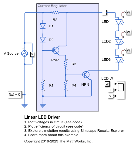
Linear LED Driver
A LED driver based on a linear current regulator. The scope shows the light and current output and the supply voltage. The output comes into regulation for a supply voltage greater than about 12V.
Assumptions and Limitations
When you select
Use I-V curve data pointsfor the Parameterization parameter, choose a pair of voltages near the diode turn-on voltage. Typically this is in the range from 0.05 to 1 Volt. Using values outside of this region may lead to numerical issues and poor estimates for IS and N.You might need to use nonzero ohmic resistance and junction capacitance values to prevent numerical simulation issues, but the simulation might run faster with these values set to zero.
The dissipated power also contains the optical output power (W). As a consequence, the block includes the optical output power in the heat generation inside the device.
If you set the Modeling option parameter to
Show thermal
            port
, the Light-Emitting Diode block overestimates the heat injected into the device. This overestimation occurs because the block includes the emitted light power from the W port as part of the heat dissipation.
Ports
Output
Conserving
Parameters
References
[1] H. Ahmed and P.J. Spreadbury. Analogue and digital electronics for engineers. 2nd Edition, Cambridge University Press, 1984.
[2] G. Massobrio and P. Antognetti. Semiconductor Device Modeling with SPICE. 2nd Edition, McGraw-Hill, 1993.