Plot Basic I-V Characteristics of Semiconductor Blocks
You can plot the basic I-V characteristics of semiconductor blocks without building a complete model. Use the plots to explore the impact of your parameter choices on device characteristics. If you parameterize the block from a data sheet, you can compare your plots to the data sheet to check that you parameterized the block correctly. If you have a complete working model but do not know which manufactured part to use, you can compare your plots to data sheets to help you decide.
To plot the basic characteristics, double-click a semiconductor block in your model that supports this option and, in the Utilities section, click the Plot button next to the Basic characteristics parameter. (since R2026a)
Before R2026a: You right-click the block and select Electrical > Basic Characteristics from the context menu.
The software computes a set of bias conditions using the block parameter values and then opens a figure window containing a plot of the DC I-V characteristics for the block. For example, the Basic characteristics parameter generates this figure for the N-Channel MOSFET block with default parameter values.
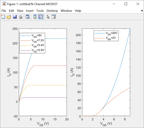
If you change the block parameter values and plot the characteristics again, the plot
opens in a new window. You can compare the plots side-by-side to see how the parameter
values affect the I-V characteristics. For example, if you set the Gate-source
voltage, Vgs, for R_DS(on) parameter of the N-Channel
MOSFET block to 20
V, and click the Plot button next to the
Basic characteristics parameter again, you generate this
plot.

The Basic characteristics parameter is available in these semiconductor blocks.
| Block | Modeling option Parameter Values | Additional Capabilities of the Basic characteristics Option |
|---|---|---|
| Diode | No thermal port | None |
| IGBT (Ideal, Switching) | No thermal port or Show thermal
port |
For more information, see Plot Additional Basic Characteristics of Ideal Semiconductors. |
| MOSFET (Ideal, Switching) | No thermal port or Show thermal
port |
For more information, see Plot Additional Basic Characteristics of Ideal Semiconductors. |
| N-Channel IGBT |
Full I-V and capacitance characteristics | No thermal
port | None |
| N-Channel MOSFET | Threshold based or Surface
potential based | None |
| P-Channel MOSFET | Threshold based or Surface
potential based | None |
| N-Channel LDMOS FET | No thermal port | None |
| P-Channel LDMOS FET | No thermal port | None |
| N-Channel JFET | No thermal port | None |
| P-Channel JFET | No thermal port | None |
| NPN Bipolar Transistor | No thermal port | None |
| PNP Bipolar Transistor | No thermal port | None |
| Light-Emitting Diode | No thermal port | Plots current versus optical power |
| Photodiode | No thermal port | Plots I-V characteristics at different flux densities |
Note
In the N-Channel MOSFET and P-Channel
MOSFET blocks, you can also perform an in-depth study of the block
characteristics and match the block behavior to a set of target characteristics. To
perform an in-depth study of the block characteristics, set the Modeling
option parameter to Surface-potential-based
and, in the Utilities section, click
the Explore button next to the
Characteristics parameter. (since R2026a) For more information
about this option, see MOSFET Characteristics Viewer.
Plot Additional Basic Characteristics of Ideal Semiconductors
Since R2023b
The Basic characteristics parameter has additional capabilities with these blocks from the Semiconductors library:
The plots you generate with the Basic characteristics parameter depend on the values you specify for the Modeling option, On-state behavior and switching losses, and Integral protection diode parameters of the block.
To plot only the on-state and off-state I-V characteristics of the switching device,
set the Modeling option parameter to No thermal
port and set the Integral protection diode
parameter to None. Then, in the
Utilities section, click the
Plot button next to the Basic
characteristics parameter. (since R2026a) For example, clicking the
Plot button next to the Basic
characteristics parameter generates this plot for the
IGBT (Ideal, Switching) block with default parameter
values.

You can also plot the on-state and off-state I-V characteristics of an integral
protection diode. Set the Integral Protection Diode parameter to
Diode with no dynamics or Diode with charge
dynamics. The Basic characteristics option
plots the I-V characteristics of the switching device and the integral protection diode
side-by-side.

You can also generate surface plots of the turn-on energy loss and turn-off energy
loss as functions of the on-state current and off-state voltage. Set the
Modeling option parameter to Show thermal
port and set the On-state behavior and switching
losses parameter to Specify constant values.
The Basic characteristics option opens the surface plots in
this figure in a separate window to the I-V characteristics plots.

If you set the On-state behavior and switching losses parameter
to Tabulate, the Basic
characteristics option plots the results over a range of temperatures.
Surface plots for different temperatures open in different windows. The I-V
characteristics plots show the results for different temperatures on a single graph in
an additional window.