PFC Rectifier Controller (Three-Phase)
Libraries:
Simscape /
Electrical /
Control /
Converter Control
Description
The PFC Rectifier Controller (Three-Phase) block implements a proportional-integral-derivative (PID)-based power factor correction (PFC) rectifier controller. This block converts a three-phase AC supply into the required stable DC-link voltage and controls the reactive power drawn from the supply. To reduce harmonics, the block draws sinusoidal current. The block has an inbuilt phase-locked-loop (PLL) that tracks the angle and magnitude of the supply voltage.
For discrete-time simulation, set Sample time (-1 for inherited) to a
positive value or to -1 to inherit the sample time. For continuous-time
simulation, set Sample time (-1 for inherited) to
0.
This figure shows the circuit configuration of the PFC rectifier.
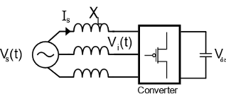
VS is the supply voltage.
IS is the supply-side current.
XL is the inductive reactance.
Vi is the inverter-side AC phase voltage.
Vdc is the DC-link voltage.
This equation defines the supply voltage VS,
where:
RL is the resistance of the filter inductor.
L is the filter inductance.
is is the inverter-side AC phase current.
Controller Structure
This diagram shows the structure of the controller.

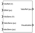
The inputs to the block are:
The output DC-link voltage reference VdcRef, measured in volts.
The per-unit reactive power reference QRef.
The measured DC-link voltage VdcSens, in volts.
The per-unit measured AC phase voltage VabcSens.
The per-unit measured AC phase current IabcSens.
The outputs are the per-unit reference voltage VabcRef and a bus containing signals for visualization.
The DC voltage controller calculates:
The per-unit d-axis reference current IdRef.
The per-unit error of the DC voltage controller VdcCntrlError.
The PLL calculates:
The phase angle pllAngle, in radians, of the measured AC phase voltage.
The per-unit magnitude pllVmag of the measured AC phase voltage.
The per-unit d-axis component of the measured AC phase voltage Vd.
The per-unit q-axis component of the measured AC phase voltage Vq.
The reactive power reference calculates the per-unit q-axis reference current IqRef.
The current controller calculates:
The per-unit reference voltage VabcRef.
The per-unit error of the d-axis current controller IdCntrlError.
The per-unit error of the q-axis current controller IqCntrlError.
Visualization
The block outputs a bus containing these seven signals for visualization:
The phase angle pllAngle, in radians, of the measured AC phase voltage.
The per-unit voltage magnitude pllVmag of the measured AC phase voltage.
The per-unit d-axis reference current IdRef.
The per-unit q-axis reference current IqRef.
The per-unit error of the DC voltage controller VdcCntrlError.
The per-unit error of the d-axis current controller IdCntrlError.
The per-unit error of the q-axis current controller IqCntrlError.
Examples
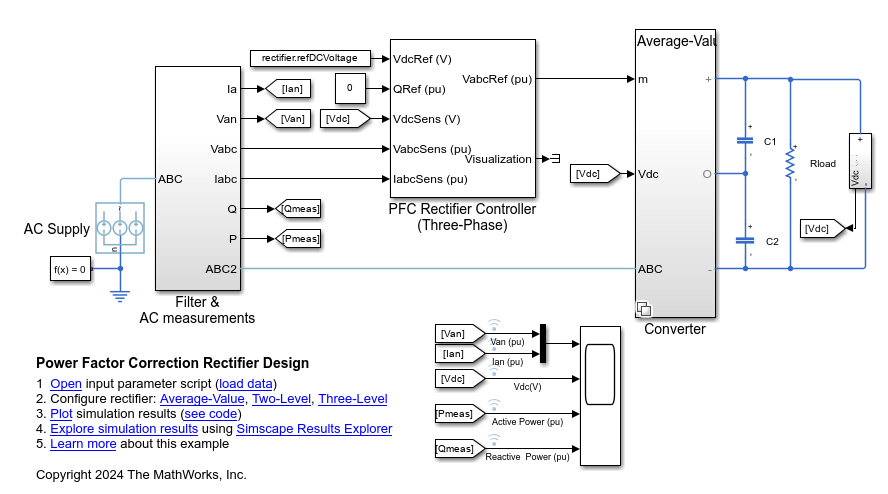
Power Factor Correction Rectifier Design
Convert a three-phase AC supply voltage into a stable DC bus voltage and control the reactive power drawn from the grid. To reduce the harmonics in the system, you use a PFC Rectifier Controller (Three-Phase) block to draw a sinusoidal current.
Ports
Input
Output
Parameters
References
[1] Siva Prasad, J. S., et al. “Vector Control of Three-Phase AC/DC Front-End Converter.” Sadhana, vol. 33, no. 5, Oct. 2008, pp. 591–613. Springer Link, https://doi.org/10.1007/s12046-008-0045-y.
Extended Capabilities
Version History
Introduced in R2024a