SM Current Controller
Discrete-time synchronous machine current PI controller
Libraries:
Simscape /
Electrical /
Control /
SM Control
Description
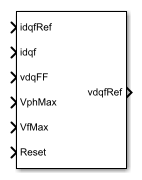
The SM Current Controller block implements a discrete time PI-based synchronous machine (SM) current controller in the rotor d-q reference frame.
Defining Equations
The block is discretized using the backward Euler method due to its first-order simplicity and its stability.
Three PI current controllers implemented in the rotor reference frame produce the reference voltage vector:
and
where:
, , and are the d-axis, q-axis, and field reference voltages, respectively.
, , and are the d-axis, q-axis, and field reference currents, respectively.
, , and are the d-axis, q-axis, and field currents, respectively.
Kp_id, Kp_iq, and Kp_if are the proportional gains for the d-axis, q-axis and field controllers, respectively.
Ki_id, Ki_iq, and Ki_if are the integral gains for the d-axis, q-axis and field controllers, respectively.
vd_FF, and vq_FF are the feedforward voltages for the d-axis and q-axis, respectively, obtained from the machine mathematical equations and provided as inputs.
Ts, is the sample time of the discrete controller.
Using PI control results in a zero in the closed-loop transfer function which can be canceled by introducing a zero-cancelation block in the feedforward path. The zero cancellation transfer functions in discrete time are:
and
Saturation must be imposed when the stator voltage vector exceeds the voltage phase limit Vph_max:
where vd, and vq are the d-axis and q-axis voltages, respectively.
In the case of axis prioritization, the voltages v1 and v2 are introduced, where:
v1 = vd and v2 = vq for d-axis prioritization.
v1 = vq and v2 = vd for q-axis prioritization.
The constrained (saturated) voltages and are obtained as follows:
and
where:
and are the unconstrained (unsaturated) voltages.
v2_max is the maximum value of v2 that does not exceed the voltage phase limit, given by
In the case that the direct and quadrature axes have the same priority (d-q equivalence) the constrained voltages are obtained as follows:
and
where
and
The constrained (saturated) field voltage is limited according to the maximum admissible value:
where:
is the unconstrained (unsaturated) field voltage.
Vf_max is the maximum allowable field voltage.
An anti-windup mechanism is employed to avoid saturation of integrator output. In such a situation, the integrator gains become:
and
where Kaw_id, Kaw_iq, and Kaw_if are the anti-windup gains for the d-axis, q-axis and field controllers, respectively.
Assumptions
The plant model for direct and quadrature axis can be approximated with a first order system.
This control solution is used only for synchronous motors with sinusoidal flux distribution and field windings.
Examples
Ports
Input
Output
Parameters
References
[1] Märgner, M., and W. Hackmann. "Control challenges of an externally excited synchronous machine in an automotive traction drive application." Emobility-Electrical Power Train, 2006, pp. 1-6.
Extended Capabilities
Version History
Introduced in R2017b
