Build and Simulate Composite and Expanded Three-Phase Models
In this example, you build and analyze a simple Simscape™ Electrical™ model that simulates the behavior of a three-phase AC voltage source driving a purely resistive three-phase load. You then modify the load in this model to change it to:
A reactive three-phase load
A resistive three-phase load expanded into individual phases
An expanded three-phase load that does not have equal resistance in each phase
To see the completed version of the model you create in this example, at the MATLAB® command prompt, enter SimpleThreePhaseModel
.
Select System Component Blocks and Build a Resistive Three-Phase Model
Open the Simulink® Start page. In the MATLAB Home tab, select the Simulink button. Alternatively, at the command line, enter:
simulink
In the Simscape section, find the templates that are preconfigured for modeling with Simscape Electrical. Select the Electrical Three-Phase template. A model that contains these blocks opens in the Simulink canvas.
Block
Purpose Library
Scope Display phase voltages and currents for the three-phase system. Simulink > Sinks
Electrical Reference Provide the ground connection for electrical conserving ports. Simscape > Foundation Library > Electrical > Electrical Elements
PS-Simulink Converter Convert the physical signals to Simulink signals. Simscape > Utilities
Simulink-PS Converter Convert Simulink signals to physical signals. Simscape > Utilities
Solver Configuration Define solver settings that apply to all physical modeling blocks. Simscape > Utilities
Grounded Neutral (Three-Phase) Provide an electrical ground connection for each phase of the three-phase system. Simscape > Electrical > Connectors & References
Line Voltage Sensor (Three-Phase) Measure the line-line voltages of a three-phase system and output a three-element physical signal vector. Simscape > Electrical > Sensors & Transducers
The model also contains two links that you can double-click to access blocks from Simscape and Simscape Electrical libraries. For more information on using templates for modeling with Simscape Electrical, see Modeling Analog Circuit Architectures, Mechatronic Systems, and Electrical Power Systems Using Simscape Electrical.
Delete the Simulink-PS Converter and Line Voltage Sensor (Three-Phase) blocks.
Add these blocks to the model.
Block
Purpose Library
RLC (Three-Phase) Model the resistive, inductive, and capacitive properties of the three-phase load. Simscape > Electrical > Passive > RLC Assemblies
Current Sensor (Three-Phase) Convert the electrical current flowing in each phase of the three-phase load into a physical signal proportional to that current. Simscape > Electrical > Sensors & Transducers
Phase Voltage Sensor (Three-Phase) Convert the voltage across each phase of the three-phase system into a physical signal proportional to that voltage. Simscape > Electrical > Sensors & Transducers
Voltage Source (Three-Phase) Provide an ideal three-phase voltage source that maintains a sinusoidal voltage across its output terminals, regardless of the current flowing in the source. Simscape > Electrical > Sources
Copy the PS-Simulink Converter and Grounded-Neutral (Three-Phase) blocks by right-clicking them and dragging them to new locations on canvas.
Add a second input port to the Scope block by clicking its input side and selecting the interactive cue that appears.
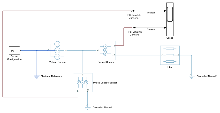
Connect the blocks as shown.
Remove the on-canvas annotations titled Open Simscape Library and Open Simscape Electrical Library. Save the model using the name
MySimpleThreePhaseModel
.The blocks in this model use composite three-phase ports. For more information, see Three-Phase Ports.
Specify Simulation Parameters
As with Simscape models, you must include a Solver Configuration block in each topologically distinct physical network. This model has a single physical network, so use one Solver Configuration block.
In the Solver Configuration block, select Use local solver and set Sample time to
0.0001
.In Simscape-based models, the local solver is a sample-based solver that represents physical network states as discrete states. For most Simscape Electrical models, the local solver is an appropriate first choice. The solver updates block states once per simulation time step, as determined by Sample time. For simulation of a 60-Hz AC system, an appropriate sample time is a value in the order of
1e-4
. For more information on solver options, see Solver Configuration.If you prefer to use a continuous solver instead of a discrete solver, clear the Use local solver check box in the Solver Configuration block. The simulation then uses the Simulink solver specified in the model configuration parameters (Modeling > Model Settings). For Simscape Electrical models, an appropriate solver choice is the moderately stiff solver ode23t. For a 60 Hz AC system, specify a value for Max step size in the order of
1e-4
. For more information, see Variable-Step Continuous Explicit Solvers.In the Simulink Editor, set the simulation Stop time to
0.1
.
Load Impedance Parameters
The RLC block models resistive, inductive, and capacitive characteristics of the three-phase load. Using the Component structure parameter, you can specify a series or parallel combination of resistance, inductance, and capacitance.
In the RLC block, the defaults are:
Component structure —
R
.Resistance —
1
Ω.
Using the default Component structure value,
R
, models a three-phase load that is purely resistive in nature. The
resistance in each phase is 1
Ω.
Specify Display Parameters
Sensor blocks in the model convert the current and voltage in each phase of the three-phase system to proportional physical signals. PS-Simulink Converter blocks convert the physical signals into Simulink signals for the Scope block to display.
Of these three types of blocks, only the converter blocks have parameters. For this example:
Set Output signal unit of the PS-Simulink Converter1 block to
V
. This setting ensures that the block outputs a signal with the same magnitude as the voltage signal that enters it.Set Output signal unit of the PS-Simulink Converter2 block to
A
. This setting ensures that the block outputs a signal with the same magnitude as the current signal that enters it.
Label the input signals to the Scope block. Double-click each line, and type the appropriate label,
Voltages
orCurrents
, as shown in the model graphic.
You are ready to simulate the model and analyze the results.
Simulate and Analyze the Resistive Three-Phase Model
Save the model.
Simulate the model.
View the phase currents and voltages. Double-click the Scope block.
From the scope menu, select View > Configuration Properties. Set Layout to 1-by-2 display.
To scale the scope axes to the data, click the Autoscale button .
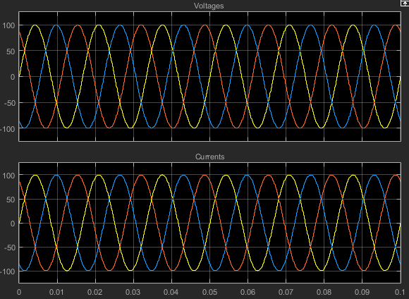
In this simulation, the Component structure parameter of the RLC (Three-Phase) block specifies that the electrical characteristics of the three-phase load are purely resistive. Therefore, for each phase of the three-phase system, the voltage and current remain in phase with each other. Because the resistance in each phase is 1 Ω, the magnitude of the phase voltage is equal to the magnitude of the phase current.
Simulate and Analyze a Reactive Three-Phase Model
You can modify the model to create a reactive load. A reactive load has inductive or capacitive characteristics.
Save this version of the model using the name
SimpleThreePhaseModelReactive
.In the RLC (Three-Phase) block, set:
Component structure to
Series RL
Inductance to
0.002
Simulate the model.
View the simulation results. Autoscale the scope axes.
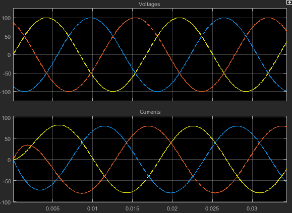
Examine the results in closer detail. For example, click the Zoom button and drag a box over the first third of one of the plots.
The electrical characteristics of three-phase load are no longer purely resistive. Because the load has an inductive characteristic, the current flowing in each phase lags the voltage.
Create an Expanded Balanced Three-Phase Model
Open the resistive three-phase model
MySimpleThreePhaseModel
that you initially created.Delete the RLC (Three-Phase) block.
Drag two copies of the Phase Splitter block into the model from the Simscape > Electrical > Connections & References library.
Flip one of the Phase Splitter blocks horizontally. Select the block. In the toolstrip, on the Format tab, click Flip left-right .
Drag a Resistor element into the model from the Simscape > Foundation Library > Electrical > Electrical Elements library.
To create space for more components, hide the Resistor element label. Right-click the resistor and select Format > Show Block Name to clear this option.
Make two more copies of the Resistor element.
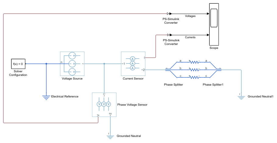
Connect the components as shown.
Save this version of the modified model using the name
SimpleThreePhaseModelExpandedBalanced
.This model name reflects that the load previously modeled by the RLC block is now expanded into individual phases. The load is still balanced, that is, there is equal resistance in each phase.
Create an Expanded Unbalanced Three-Phase Model
Unbalance the load in
SimpleThreePhaseModelExpandedBalanced
by changing the resistance in one phase. Double-click the phase-c resistor element. Change Resistance to2
.Save this version of the modified model using the name
SimpleThreePhaseModelExpandedUnbalanced
.This model name reflects that the three-phase load previously modeled by the RLC block is expanded into individual phases. The load is unbalanced, that is, the resistance in one of the phases is higher than in the other two.
Simulate the Expanded Balanced and Unbalanced Models and Analyze the Results
Simulate the
SimpleThreePhaseModelExpandedBalanced
model. In the menu bar of the Simulink Explorer, click the Run button.View the simulation results. Double-click the Scope block.
To scale the scope axes to the data, click the Autoscale button .
In the
SimpleThreePhaseModel
, the Component structure parameter of the RLC (Three-Phase) block specifies that the three-phase load is purely resistive. In this version of the model, the load is expanded into an individual resistive element for each phase, but the resistance in each phase is unchanged. For each phase of the three-phase system, the voltage and current remain in phase with each other. Because the resistance in each phase is1
Ω, the magnitude of the phase voltage is equal to the magnitude of the phase current.Comparing these results with the results for the three-phase resistive model shows that a block with composite three-phase ports, the RLC (Three-Phase) block in the original model, produces results with the same fidelity as that of expanded phases.
Open the
SimpleThreePhaseModelExpandedUnbalanced
model.Simulate the model. Autoscale the scope axes.
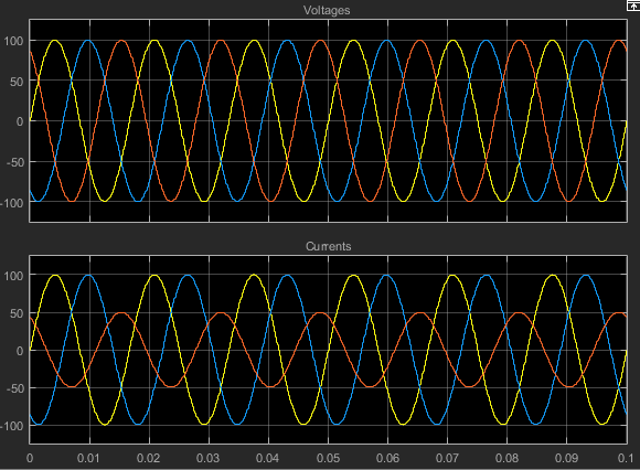
In this version of the model, the c-phase of the three-phase load has twice the resistance of the other two. Therefore, half as much current flows in that phase, as the second plot shows. However, because the load remains purely resistive, the voltage and current remain in phase with each other.