Mask Simulink Based States
Use Simulink® based states to model hybrid dynamic systems or systems that switch between periodic and continuous-time dynamics. In your Stateflow® chart, you can combine Simulink based states with switching logic that uses transitions. For more information about Simulink based states, see Simulink Subsystems as States.
You can use masks with linked Simulink based states to control the parameters for various inputs and outputs to your system at the chart level. Masking is especially beneficial for systems that have reusable components, as it enables the customization of parameters to fit distinct scenarios or use cases. Masking allows you to reuse components while maintaining the ability to fine-tune the behavior of each instance of the Simulink based state.
This example shows how to modify a Stateflow chart to update the parameters of a Simulink based state system.
Create a Masked Simulink Based State
Open the Pole Vaulter example and its corresponding library. At the command prompt, type:
openExample("sf_pole_vault")
openExample("sf_pole_vault_lib")
This example models a pole vaulter. For a detailed explanation of the model, see Access Block State Data.
To unlock the library, click the Locked Library button. Select
the Run_up subsystem. In the toolstrip, open the Subsystem
Block tab. Click the Create Mask button. The mask editor
appears. For more specifics about the mask editor capabilities, see Mask Editor Overview (Simulink).
In the Controls pane, use the Promote
One-to-One button and add one parameter for the velocity of the vaulter and one
parameter for the starting position. To add these parameters, choose
InitialCondition for both Position
and Velocity.
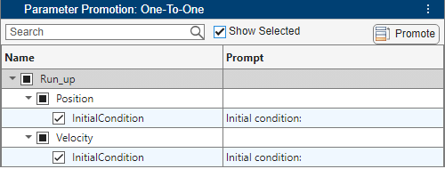
After you add the parameters, you can edit the prompt and the name.
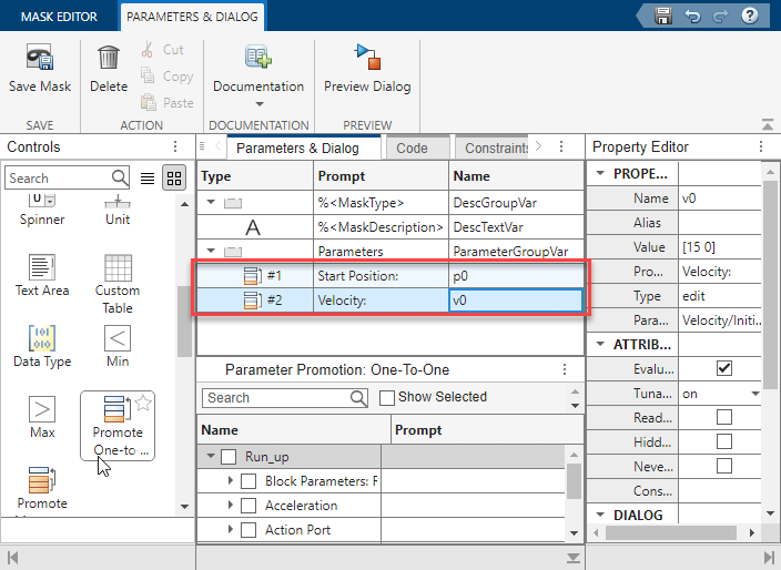
The Prompt column shows the text that appears in the block dialog for the block mask. The Name column is the name of the parameter data.
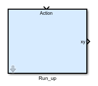
Click the Save Mask button and close the mask editor. In the
library, the Run_up block icon includes a gray arrow in the lower-left
side. This arrow indicates that there is a mask on the block.
Add a Masked Subsystem to Stateflow
In the sf_pole_vault
Simulink model, open the PoleVaulter
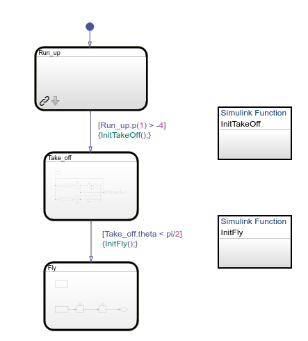
Stateflow chart. Delete the Run_up
Simulink based state, and replace it with the masked Run_up
subsystem block from the library. The new chart shows the linked and masked Simulink based state.
To update the starting position and velocity of the vaulter, double-click the updated
Run_up state. The Block Parameters window appears. In the
Parameters tab, you can update the starting position and the
velocity.
Note
The starting position for the vaulter must be a negative number, because the bar is
located at y = 0 in this example. Additionally, because the vaulter
plants his pole at y = -4, use a number smaller than
-4.
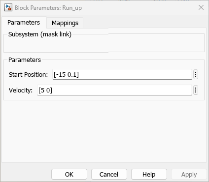
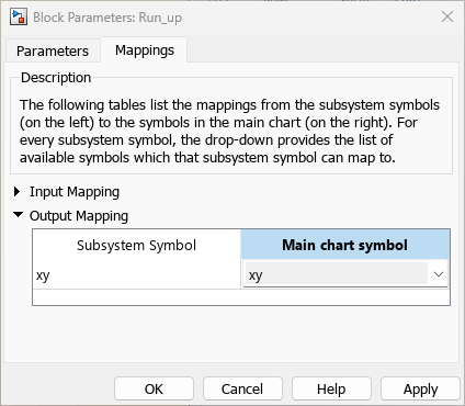
In the Mappings dialog, update the output mapping so that the Subsystem Symbol corresponds to the correct Main chart symbol.
View the Results
After running the model, open the XY Graph block.
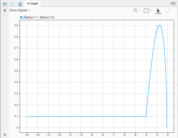
The graph shows that the vaulter started at -15, because the velocity
is 5, the vaulter did not reach a height over
1.
Limitations
Masked Simulink based states do not support:
Self-modifiable masks.
Drawing Commands tab.
Undo or redo in the Mask Dialog.